
Chapter 5 - PC Assembly - Part II
PSU, Fans, and Wiring
This section will cover installation of the power supply and motherboard, and shows options for fan installation and video card installation.
Adding the Power Supply
With the motherboard assembled and tested, now we can move forward with affixing the devices in the case. First we'll start with the power supply.
Do you have a modular or non-modular power supply? A modular or semi-modular power supply is easier to work with as the cables can be added as you go long. Non-modular power supplies may require you to move the unneeded cables out of the way until they're connected, with the benefit of the inability to misplace them because they're permanently attached. Begin by getting your power supply. If it is to be mounted at the top of your case, the exhaust fan can be aimed upwards if there is a vent at the top of the case. Otherwise ensure the PSU exhaust fan is aiming downwards. Here is an EVGA brand power supply going into my case:
Do you have a modular or non-modular power supply? A modular or semi-modular power supply is easier to work with as the cables can be added as you go long. Non-modular power supplies may require you to move the unneeded cables out of the way until they're connected, with the benefit of the inability to misplace them because they're permanently attached. Begin by getting your power supply. If it is to be mounted at the top of your case, the exhaust fan can be aimed upwards if there is a vent at the top of the case. Otherwise ensure the PSU exhaust fan is aiming downwards. Here is an EVGA brand power supply going into my case:
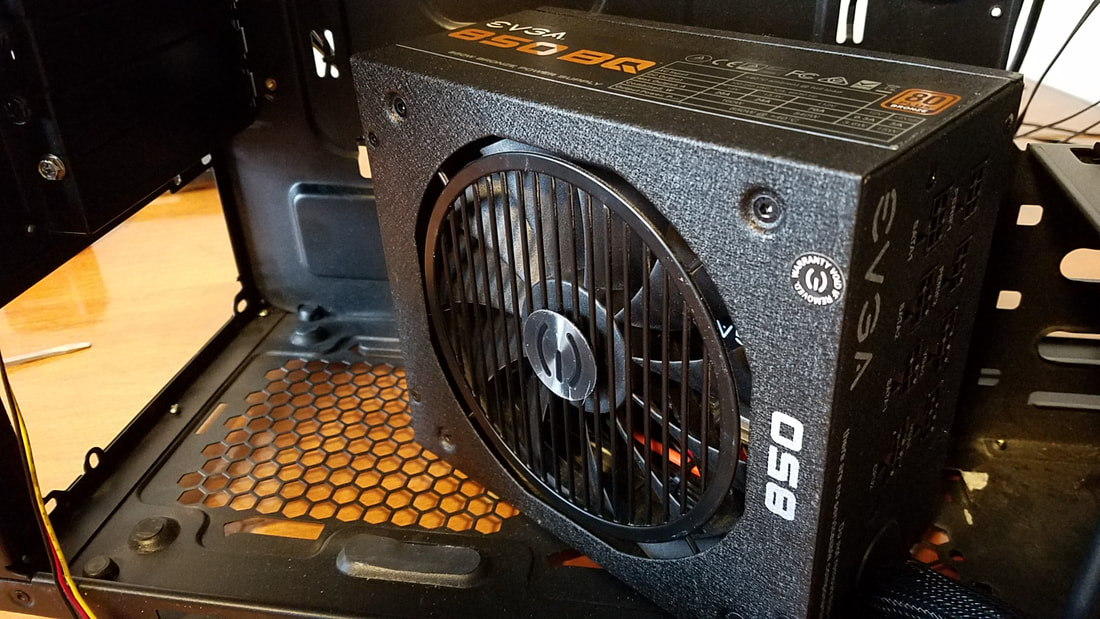
Here it is again inserted all the way against the back of the case. Check to ensure the PSU fan is aiming downwards if your case has a vent for the hot air to pass through.
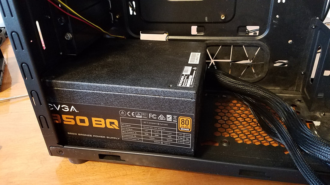
You may need to adjust it a bit to ensure that the holes in the power supply line up with the holes in the case for the power supply. You'll notice on the case that there are extra holes to secure the power supply. This is because some power supplies can be mounted in either direction and to accommodate cases that don't have a vent for the PSU fan to exhaust hot air.
Apply four screws to the power supply to secure it to the case:
No matter what type of power supply you use, you can move the cables out of the way:
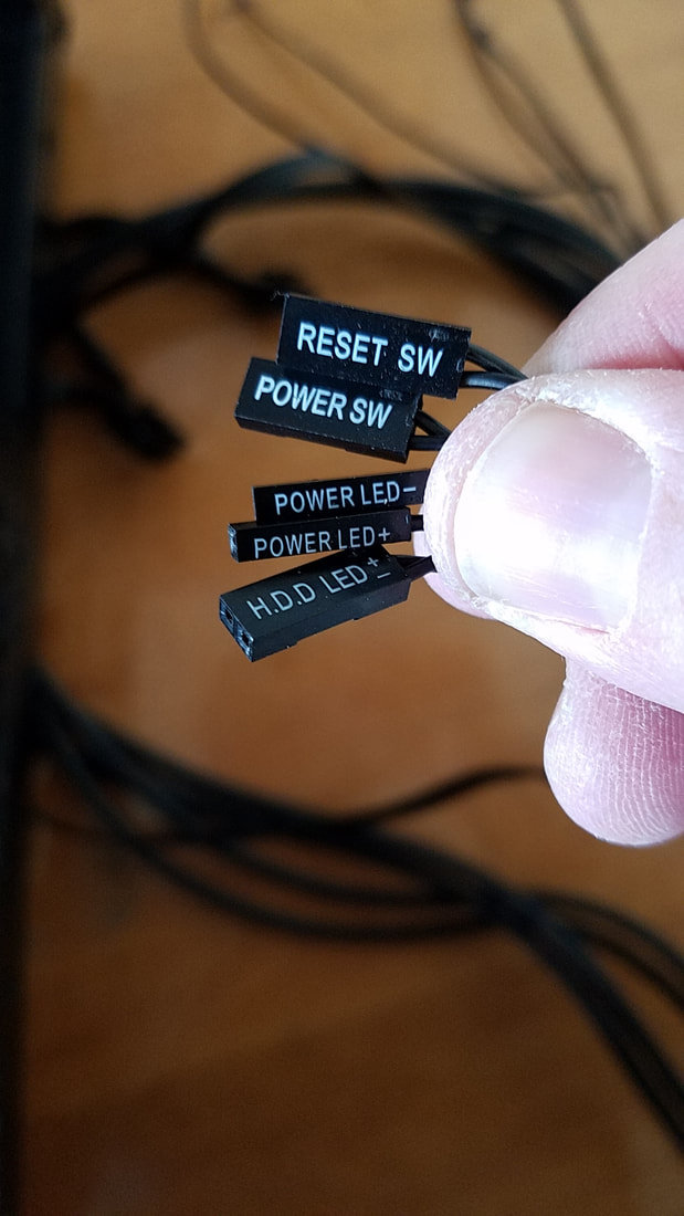
The above photo shows cables moved through a rubber grommet. If your case doesn't have an opening or anything similar, you can move them to the front or somewhere else out of the way, as you'll be needing space to insert and secure the motherboard and other devices. You'll also want to gather all of the front panel connectors and move those out of the way as well. This includes the power and reset buttons, any USB 2.0 and 3.0 ports, any LED indicators, and audio connectors if equipped:
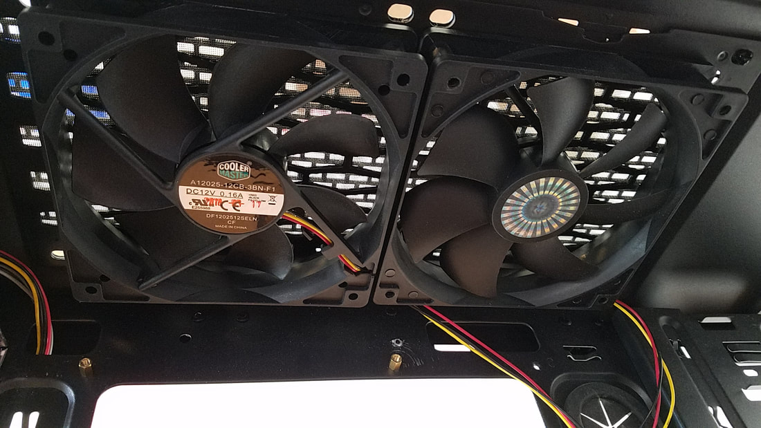
Fans and Airflow
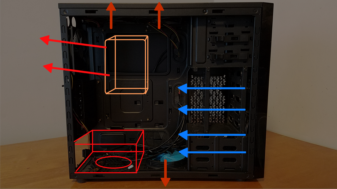
At this point we can talk about fans and airflow. The way I typically run my rigs is having the intake come through the front (blue arrows). This brings in air to cool the CPU (orange, center). The CPU pushes any hot air out the back (Red arrows, left).
The intake can also help cool the PSU (bottom left, red) but the PSU typically does not get hot at all. The fan at the bottom of the case can also push any air out of the bottom. You can mount any bottom fan to pull any cold air in front the bottom, but consider that dust usually resides underneath which can be brought into the case if a filter is not supplied on the case. Top fans above the CPU have the same effect. They can push any hot air upwards (helpful, as heat naturally rises), or pull air in from above the case.
The intake can also help cool the PSU (bottom left, red) but the PSU typically does not get hot at all. The fan at the bottom of the case can also push any air out of the bottom. You can mount any bottom fan to pull any cold air in front the bottom, but consider that dust usually resides underneath which can be brought into the case if a filter is not supplied on the case. Top fans above the CPU have the same effect. They can push any hot air upwards (helpful, as heat naturally rises), or pull air in from above the case.
Now where to put the fans? That can vary. Some boards may only have one or two additional headers for fans, so if you wanted to add more fans you would need to either purchase a fan controller for the front of your case, (assuming you have a case with a spare 5.25" slot for the controller, or connect a fan to one of the Molex plugs from the power supply. Some fans have a Molex connector while others have a 3- or 4-pin connector. If yours has the pinned connector but you need to connect it to a Molex plug, you can pick up a Molex adapter for a few dollars on eBay. Remember that you don't need to affix a fan to every available spot in the case, and that sometimes more fans equates to more noise.
Below are photos of the fan headers on my Intel board:
Below are photos of the fan headers on my Intel board:
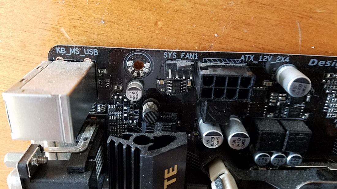
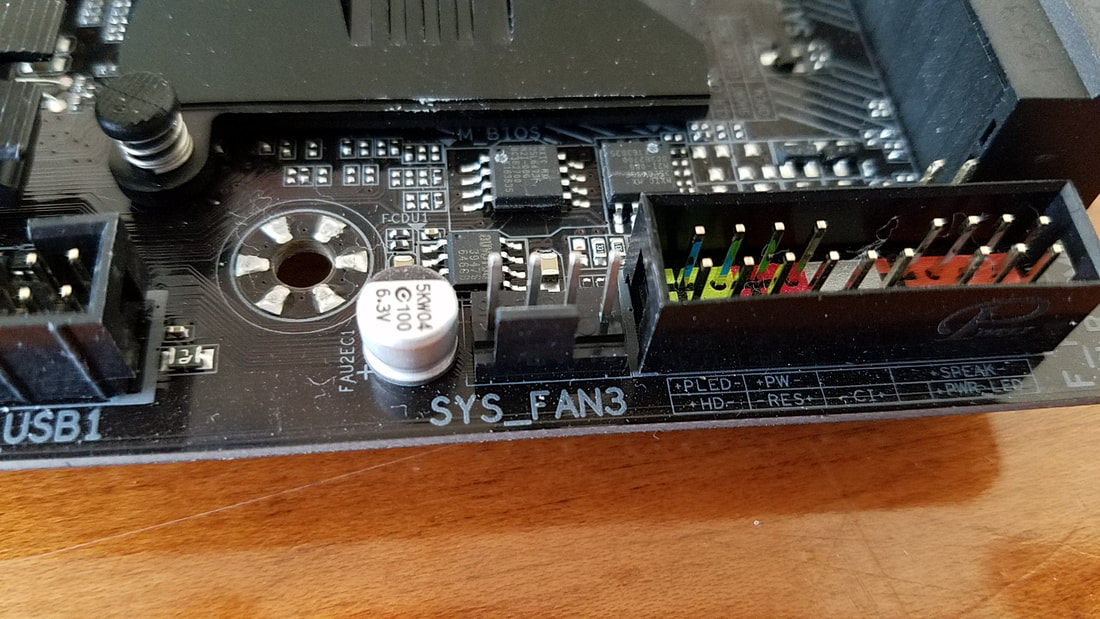
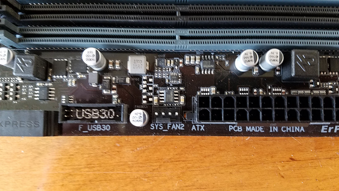
These headers will power fans with both 3-pin and 4-pin (below) connectors:
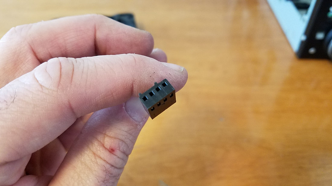
Notice the two plastic teeth on the top. This is used to orient the connector to the fan header to prevent improper connection.
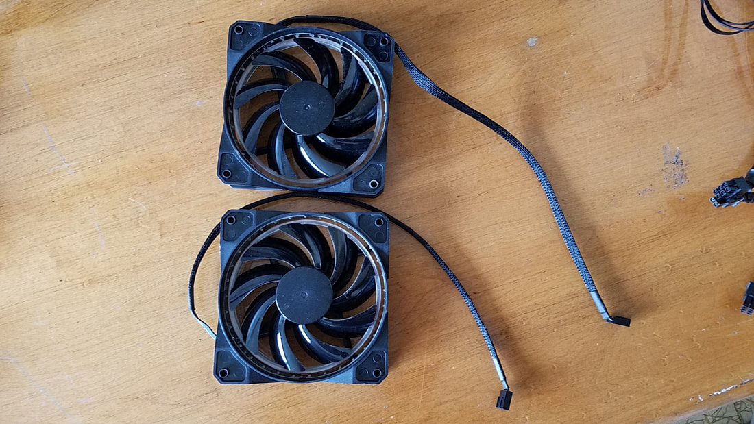
As a preventive measure you can partially wrap fan cords around the chassis of the fan itself. By doing so ahead of time, you'll have less cables getting in the way of other cables, it won't appear as messy, and will heave a cleaner appearance. Simply measure the distance of the fan cable from where you plan on connecting it to while making sure it has some play to it.
As a preventive measure you can partially wrap fan cords around the chassis of the fan itself. By doing so ahead of time, you'll have less cables getting in the way of other cables, it won't appear as messy, and will heave a cleaner appearance. Simply measure the distance of the fan cable from where you plan on connecting it to while making sure it has some play to it.
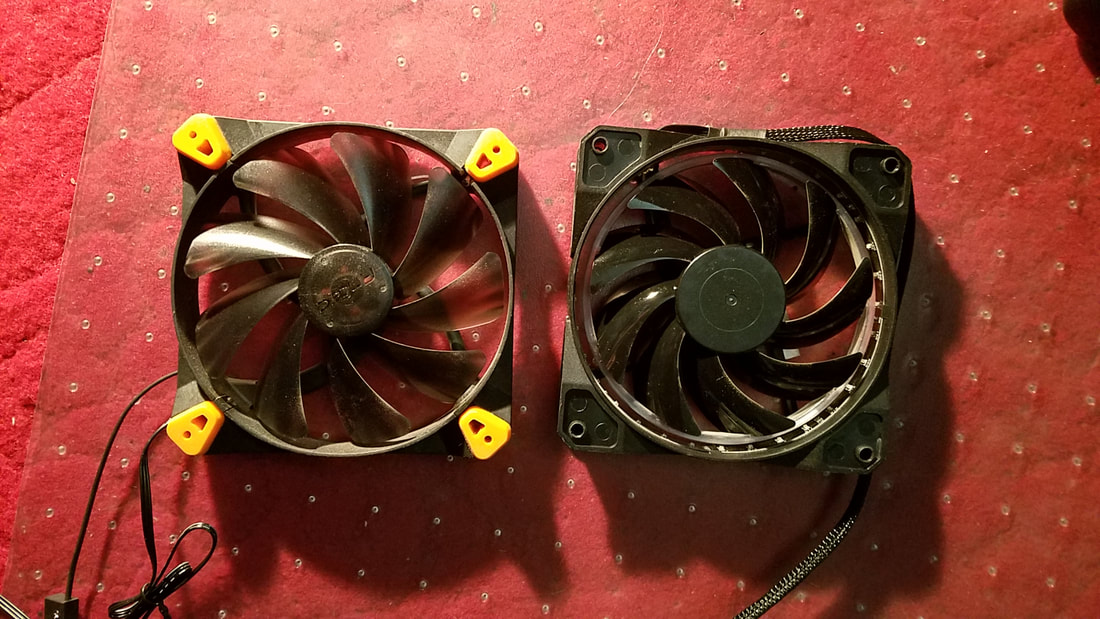
Noise can be an issue sometimes. Some fans have built-in rubberized pads like the Antec True-Quiet series. The front of the fan have yellow rubberized pads (left) while the rear does not (right):
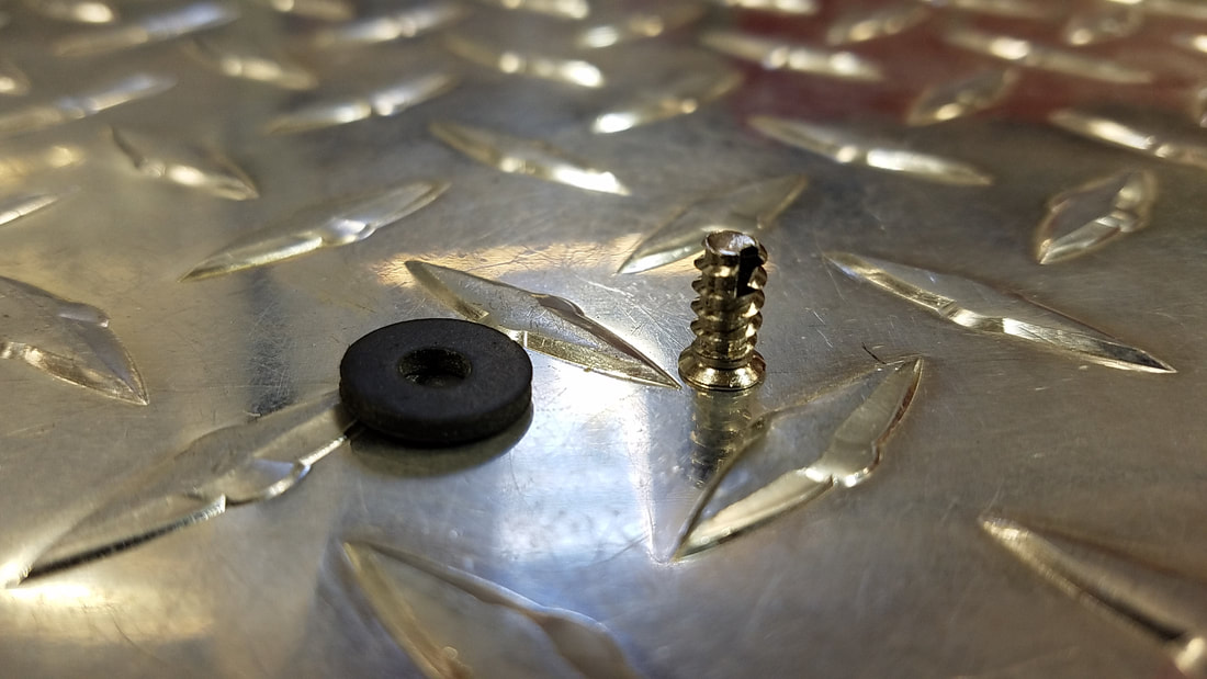
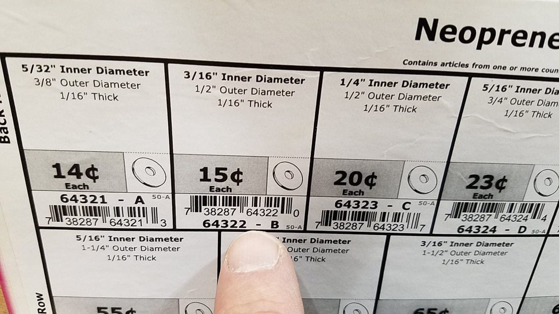
Most fans don't have built-in vibration pads. Fans should come with coarse-threaded screws, but you can separately purchase rubber washers for better noise- and vibration-dampening:
|
|
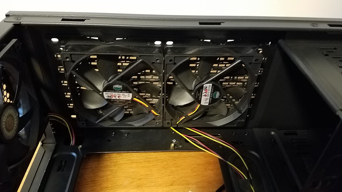
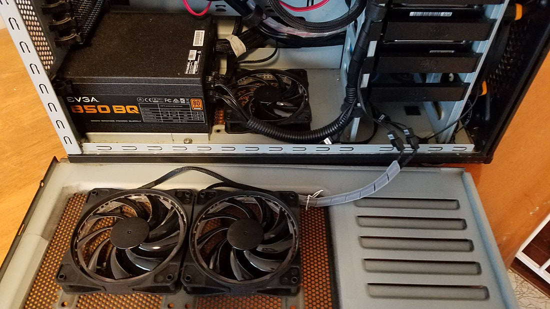
After you've determined the length of each fan cable, you can affix the fan in place with one screw, route the fan cable where needed, and attach the connector to the other device (Molex connector, 3-pin connector, 4-pin connector). The photo below shows two mounted fans. The connectors aren't showing but they are almost equal in length and going to the connectors of the fan controller. All of those cables are mounted near the front, neatly tucked away near the hard drives.
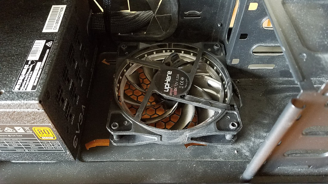
You can also have an intake/exhaust setup similar to the photo below, but I'm not sure how effective this is:
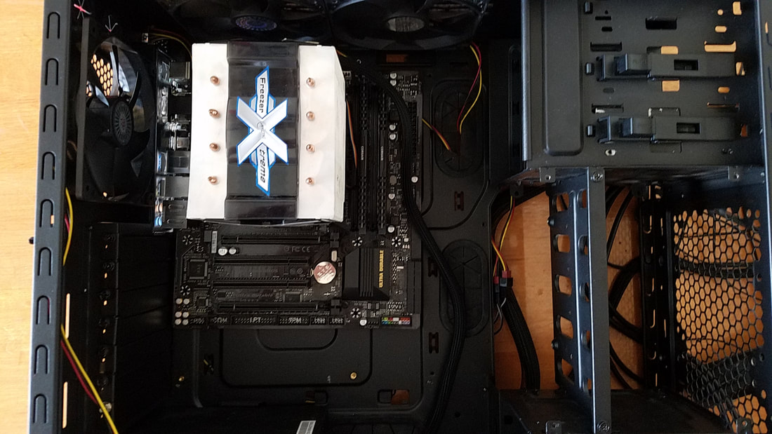
The same can be done for the bottom fan as I have it already attached to the motherboard here:
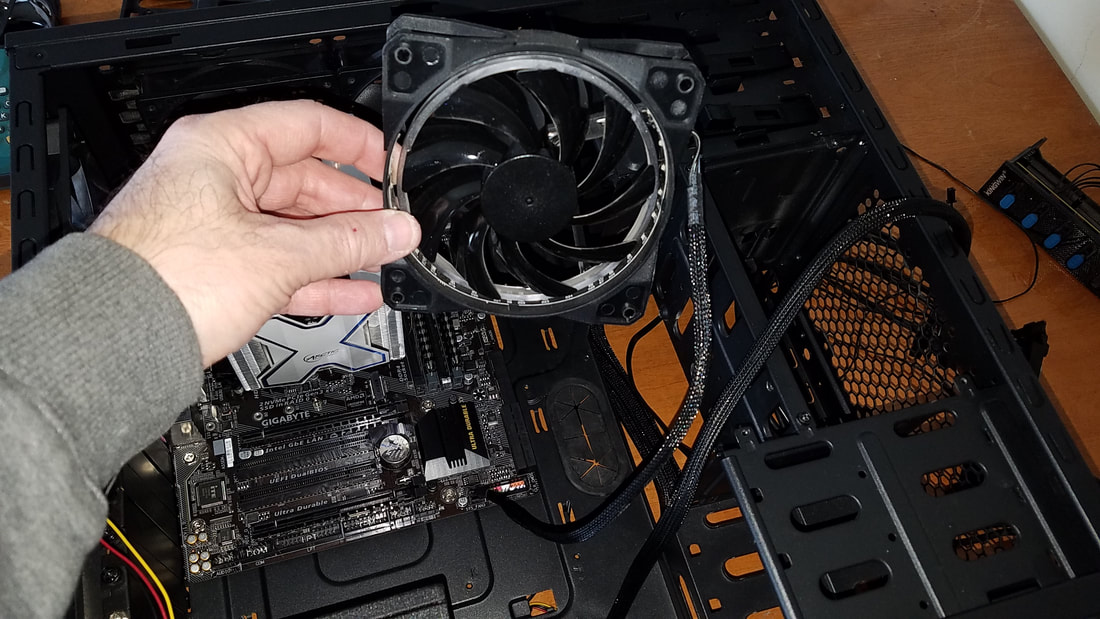
...then have the fan cable strategically wrapped around toward the side of the motherboard behind the fan chassis, then up to the fan header on the motherboard:
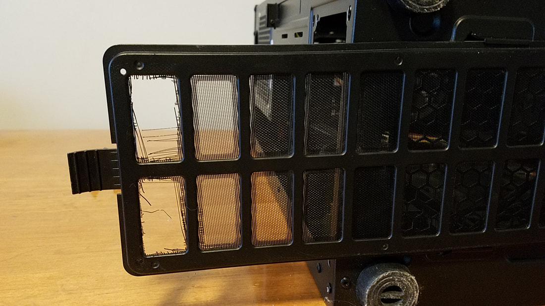
This Cooler Master N600 case has a removable filter too, however...
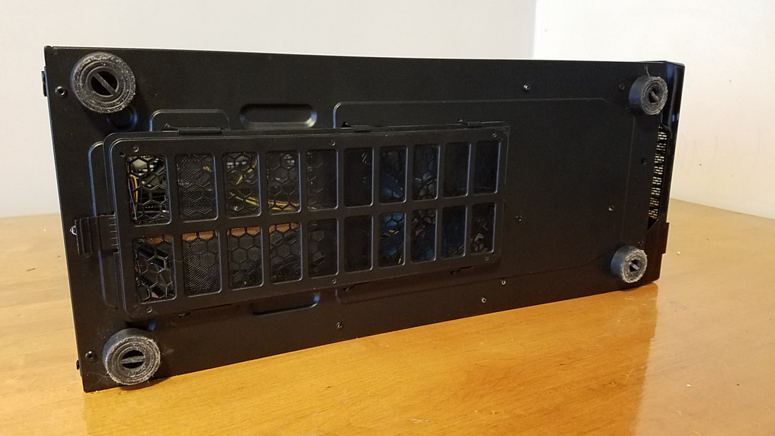
Poor engineering and me lifting and moving the case too many times caused this:
A number of cases have a grated side panel allowing you to hook up one or more fans there as well:
This can sometimes pose a spacing challenge as you'll want to ensure the chassis of the fans clears the power supply and the CPU cooler (if it sticks out).
Note that the cables from the fan are wrapped in a loom and are connected to the fan controller headers. If you're forgetful and attempt to take the panel off, you can damage the fan wires by forgetting to remove them from the headers. One of the techniques to wrap wires in a loom are in the video below:
Affixing the Backplate and Motherboard
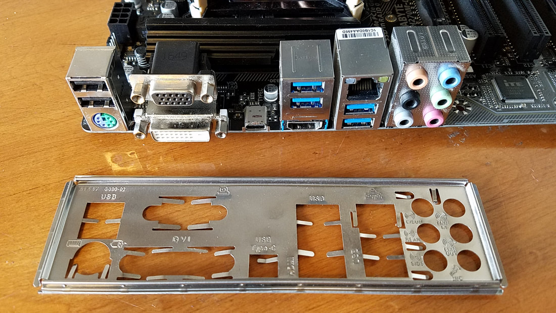
The next step is to prepare your case for the motherboard. Your motherboard will come with a backplate that conforms to the port layout of the motherboard:
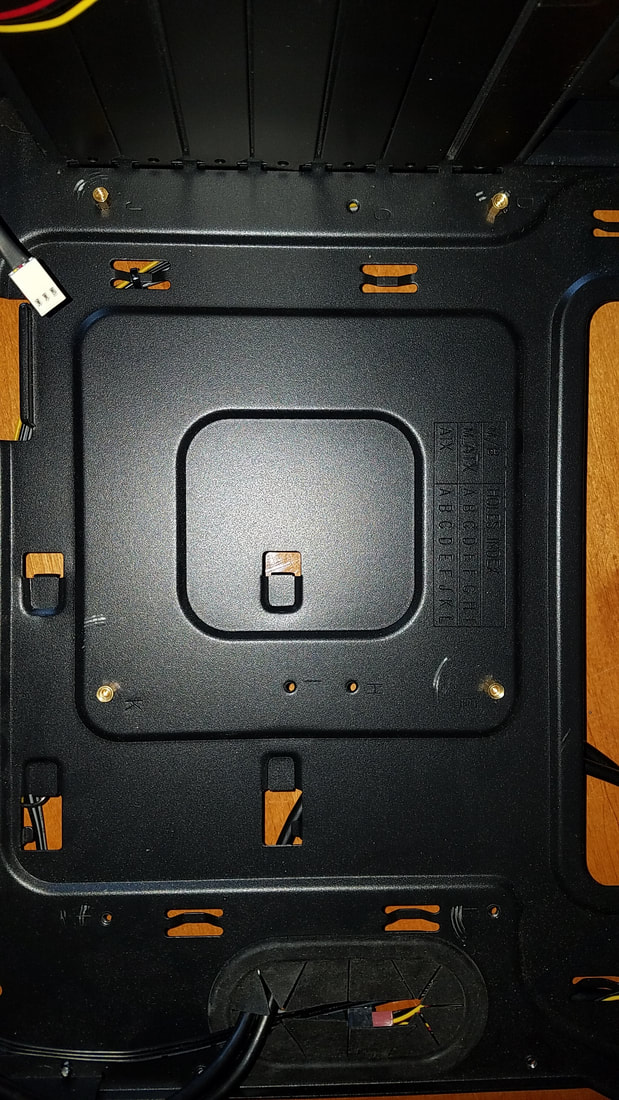
Take the backplate, make sure it's aligned properly, then begin affixing it to the case through the inside of the case:
The plate should snap in place, but if it seems off you can push it in from the outside and try again until it's set in correctly. Once that's done we can affix the standoffs to the case. The standoffs have a brassy appearance and raise the motherboard away from the side panel. In the photo below I've attached motherboard screws to the standoffs to keep them organized:
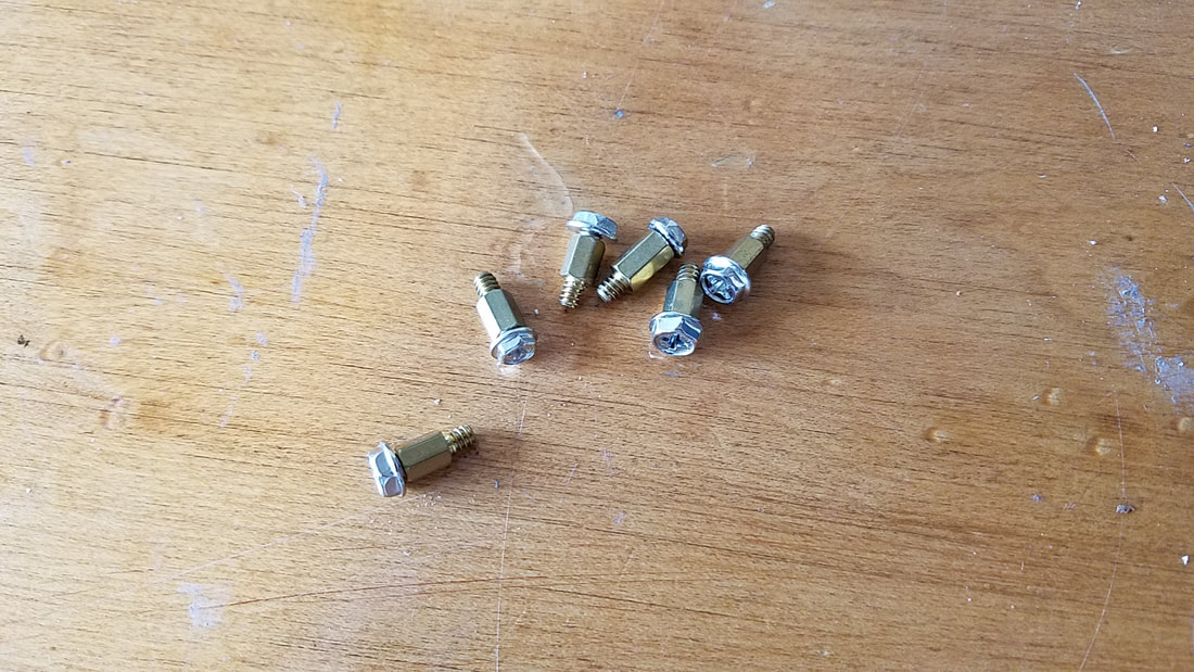
Your motherboard will come with an appropriate number of screws for the board size. Any excess standoffs and screws can be used for another PC build project.
HELPFUL HINT: The reason I attached the screws to the standoffs in the photo was because I had an assortment of existing standoffs and a larger quantity of screws. Not all screws worked with the standoffs as I even tested one screw with different standoffs and found that not all of the standoffs fit the screws. My solution was to take one standoff with different screws and keep trying them until one fit. From there I just kept them together. If I built another PC I would unattach the two from each other, affix the standoff to one hole on the case, and lay the screw on the floor in one location to let me know that the particular screw fit the particular standoff. This way I would save time down the line from having to find the right screw for the right standoff.
HELPFUL HINT: The reason I attached the screws to the standoffs in the photo was because I had an assortment of existing standoffs and a larger quantity of screws. Not all screws worked with the standoffs as I even tested one screw with different standoffs and found that not all of the standoffs fit the screws. My solution was to take one standoff with different screws and keep trying them until one fit. From there I just kept them together. If I built another PC I would unattach the two from each other, affix the standoff to one hole on the case, and lay the screw on the floor in one location to let me know that the particular screw fit the particular standoff. This way I would save time down the line from having to find the right screw for the right standoff.
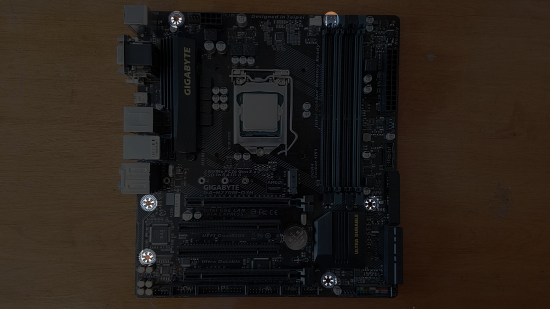
Next you'll want to find out how many standoffs are needed. I took my Intel board and counted six holes which are highlighted in the photo below:
After that I gently placed the motherboard in the case to see where I'd have to put the standoffs:
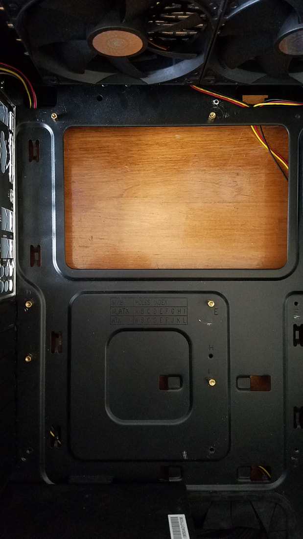
In the next photo I removed the Intel Micro_ATX board and applied standoffs to the top of the panel:
All standoffs should be initially hand-tightened, but you can use a pair of pliers to tighten it. Remember that the standoffs will have screws inserted into them to secure the motherboard, so they should be tightened appropriately:
From here you should be able to affix the remainder of the necessary standoffs to the motherboard:
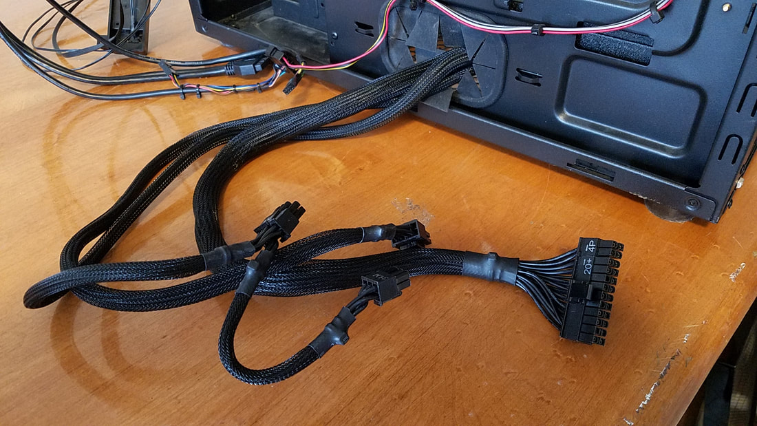
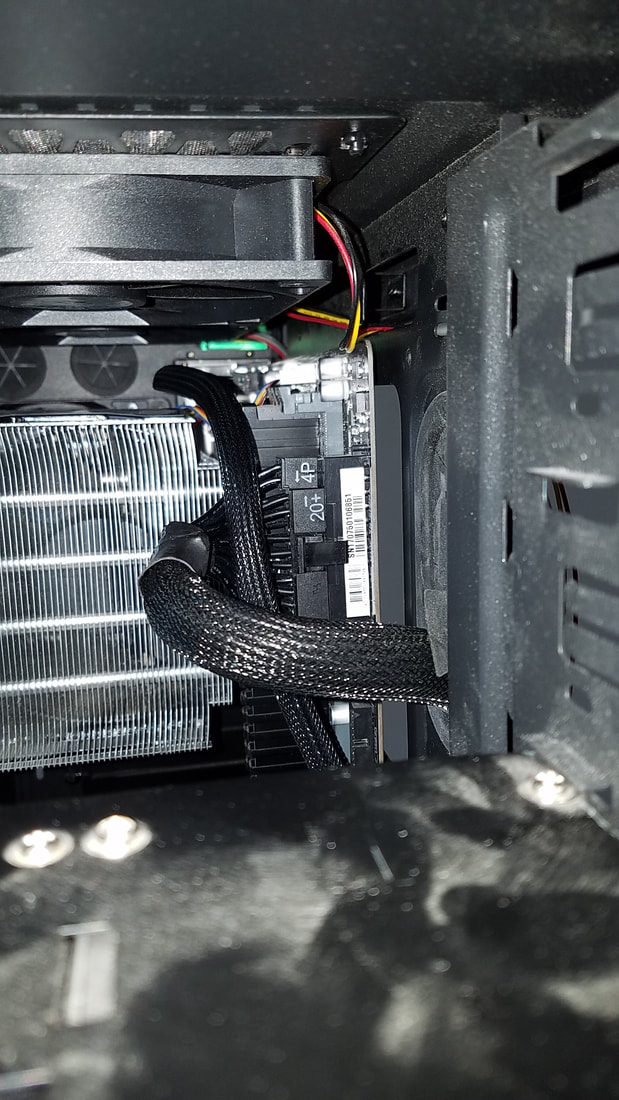
At this point you can retrieve the P4 and 24-pin Connector from the power supply and also retrieve the front panel connectors:
Now is a good time to consider cleaning up the wires for the front panel as well. Gather those together and move them out of the way, then apply the cable wrap to them so you can make your wires similar to those on the left appear cleaner and more manageable to those on the right:
|
|
You can watch the video in the previous section regarding the application of wire wrap to fan wires, which applies to all cables in the case.
There are two processes here involving cable attachment, and you can try either one at any time.
- Once you put the motherboard in the case and secure it, it's there until you loosen the screws and remove it. After it's in that position it may also be difficult to attach the P4 connector in the upper left corner just as difficult as it might be to attach the small front panel connectors to the lower right front panel headers.
- You can attach the power connectors and front panel connectors to the board ahead of time. But if you want to reroute the cables later to look cleaner, you'll just end up having to remove and reinsert them again after they've been routed.
Insert the motherboard into the PC by placing it in the upper left hand corner, ensuring the rear connectors go through the backplate:
Next ensure that the mounting holes in the board line up with the standoffs, affix screws through the motherboard to the screw standoffs without a lot of tension, and when all the screws are in, start tightening them more one by one in a reversing pattern. If you haven't already done so, attach the P4 connector, the 24-pin connector, and the front panel connectors to the motherboard.
Now if you rewire the cables after the motherboard has been mounted in the case, you may have difficulty reattaching some of the cables:
Now if you rewire the cables after the motherboard has been mounted in the case, you may have difficulty reattaching some of the cables:
Take the time to ensure all cables are inserted properly and it will cut down on time used for troubleshooting later on. It may not always be easy, but it is possible.
Once the system boots up, ensure the connected fans are running by putting your hand near each fan's exhaust side to ensure it is pushing air. Too often I've mistakenly installed the fans backwards, had to shutdown, remove and reinstall the fan. To shut down for making adjustments or to go to the next step, you can hold down the power button on the case for 5 seconds or so and it should shut the computer down entirely. After that, turn the PSU power switch off, and remove the cable from the PSU.
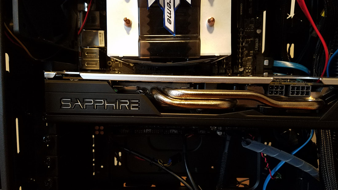
Adding a Video Card
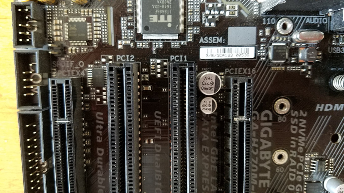
If you have a video card you'd like to test out, now's a good time to do that as well. First, look at your motherboard and identify the PCIe slots by their speed. Typically it should be the top slot among the PCIe slots. This is a rotated picture of my Intel motherboard, but you can see the "x16" label by the rightmost (uppermost) slot:
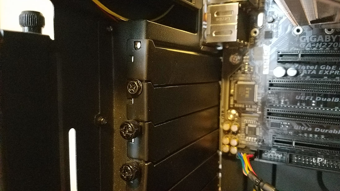
The back of cases have covers for the PCI slots. The next photo show the top cover without a screw, the one below that with a screw, and two below that with thicker screws for tightening and loosening using one's fingers. Loosen and remove the panels where your video card backplate(s) will occupy, but keep the screws handy as you'll need them shortly.
Carefully insert the video card into the PCIe slot as shown in the video below. The video depicts the card out of the computer case.
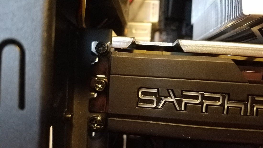
While the video is in the slot, there will still be some play to it. This is where you can affix the screws from the previous removed backplate(s) to the backplate(s) on the video card to the back of the case:
Next is to locate the power port(s) on the video card, either on the top or rear. On the RX 580 they are on the top of the card on the right:
Make the power connections, connect your monitor to the video port on the card, then fire it up! Some cards may have a fan running constantly, while others may only run when the heat threshold is triggered.
Testing
Now we can test the board again and the fans. Connect the power cord to the PSU, then turn the rear PSU switch on. Because the font panel connections have been made, press the power button on the case.
In the process of connecting cables, there's a slight chance that one or more cables may have come undone. This may cause the inability to boot your computer.
NOTHING HAPPENS, NO LIGHTS, NO SPINNING FANS
- Check to ensure the power cord to the PSU is plugged in all the way and fits snugly. Remove and reapply it if necessary.
- Ensure the other end of the power cord from the PSU is going to a wall jack or working outlet. If it's going to a surge strip / surge protector, ensure the device is powered on, and also try another open outlet on the strip.
- Look into the case and ensure the two wires of the front panel power switch are going to the two pins on the board for the power leads. If they're not fully inserted on to the two pins it may not turn on.
- While in the case, ensure the 24-pin mains and P4 connector are fully connected. Remove and reconnect if necessary.
- While unlikely, it's possible that the CPU is not firmly seated in the socket and may need adjusted. Remove the cooler, open the gate of the CPU socket, and ensure the CPU is firmly seated.
- If none of the above solutions resolve the problem, try a replacement PSU/Motherboard/CPU if necessary. It's extremely unlikely that a new part can be part of a bad batch as these components go through vigorous testing before being shipped out, but it has happened. If you have a spare component available, test these one at a time to narrow down the faulty component.
