
Chapter 5 - PC Assembly - Part I
Windows, CPU, PSU, and RAM
This chapter is longer and covers the entire assembly of a PC from start to finish. Throughout the process you'll be connecting different parts to the motherboard and case. In order to save time it's better to power on the PC at various points to ensure a part or group of parts work together as they should. This is more effective than building everything in one shot, only to power up and not get a signal, which may then require you to disassemble your project and search for the culprit. This does not cover the assembly of laptops as each laptop assembly is different.
To ensure you have all the needed parts, let's go down the list:
- Motherboard
- CPU
- Case
- PSU
- HDD/SSD
- Video Card (optional)
- SATA Cables (1 per each HDD/SSD)
Downloading Windows (Optional)
Whether you're here to strictly build a Windows-based machine or a Hackintosh, you'll need to download the Windows installer to a flash drive then install Windows to a HDD/SSD. For Hackintosh builders, having Windows installed to a separate drive will allow you to update the BIOS to the latest version when it becomes available in addition to downloading macOS if you don't already have access to a Mac. If you have an existing desktop or laptop and have any restoration CDs or DVDs, they won't work for the creation of a new system.
WARNING: On a new assembly, Windows can be installed to a new drive in order to get it up and running. But without a license key, you'll be restricted with some options. You can utilize the majority of the functions in Windows, but you will have a watermark on the lower left of your screen reminding you to activate Windows and lose the ability to change the background wallpaper and other customization options.
WARNING: On a new assembly, Windows can be installed to a new drive in order to get it up and running. But without a license key, you'll be restricted with some options. You can utilize the majority of the functions in Windows, but you will have a watermark on the lower left of your screen reminding you to activate Windows and lose the ability to change the background wallpaper and other customization options.
DOWNLOADING ON A PC:
The first step is to do a search for "Windows ISO download". The current web page directly from Microsoft can be found by clicking this link which will take you to the download page. Here's how it appears on Windows:
The first step is to do a search for "Windows ISO download". The current web page directly from Microsoft can be found by clicking this link which will take you to the download page. Here's how it appears on Windows:
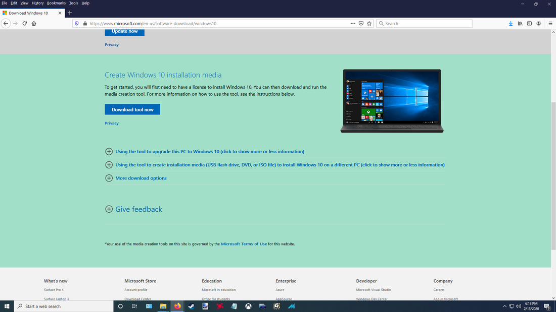
Note: The mint green background is the background color I chose in Firefox. If you haven't altered your settings it should be white.
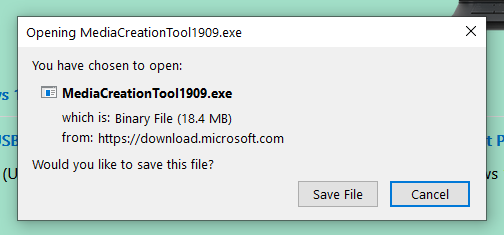
Click on the box that reads "Download tool now", then on "Save file" on the pop-up box:
Click on the box that reads "Download tool now", then on "Save file" on the pop-up box:
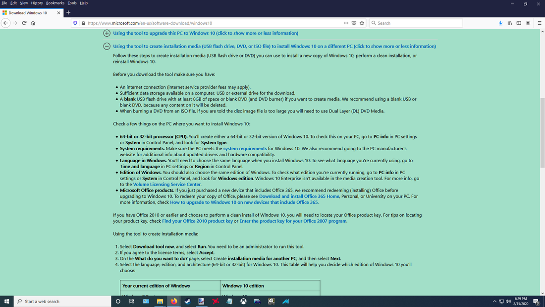
If you click on "Use the tool to create installation media..." you'll get a rundown of some important information.
The tool itself is very small and shouldn't take much time, and should appear in your Downloads folder:

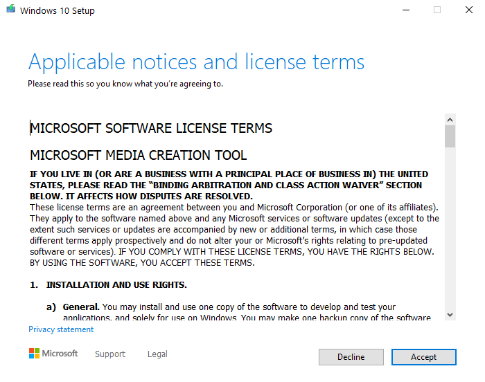
Launch the Media Creation tool and accept the license terms.
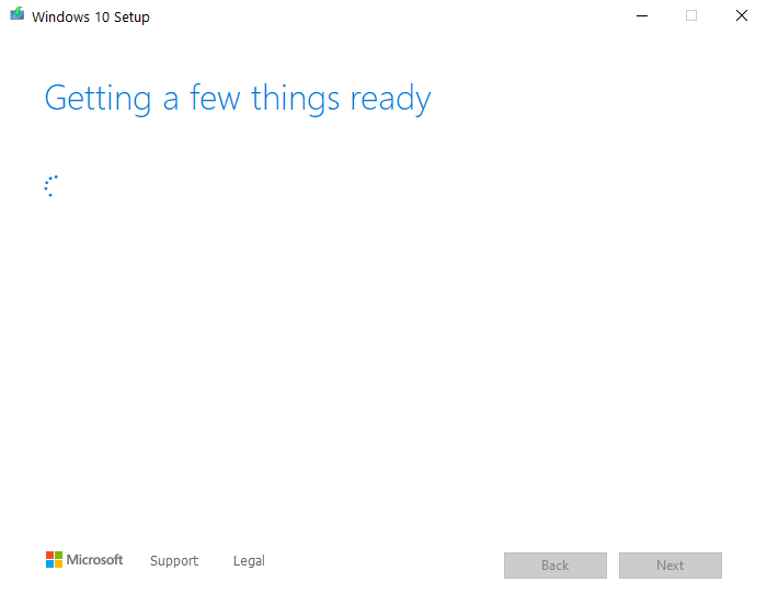
It will take a few seconds to set things up.
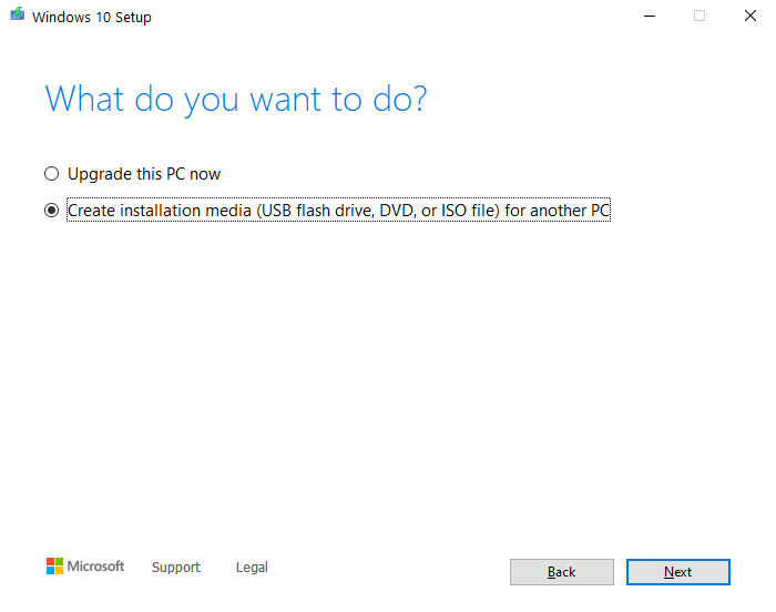
At this prompt, click the option to create installation media.
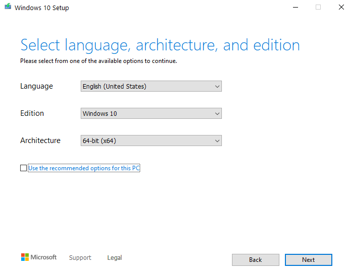
By default, the option for "Use the recommended options for this PC" will be checked. Uncheck the box, then you can change any options if needed. You'll want to keep the architecture kept at "64-bit (x64)".
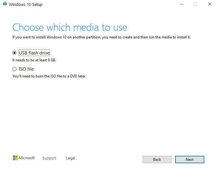
At this point, set the installation media to a flash drive. A standard DVD only holds about 4.7 GB while a dual-layer DVD holds more, but consider that USB flash drives hold much more, are faster, less-susceptible to read/write errors, and can be written to multiple times more than a DVD can. The Windows installer itself is more than 4.7 GB and would require multiple discs, and optical media is becoming more scarce. Your build may not even require a DVD drive.
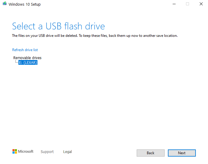
Attach your blank USB flash drive to the computer, reformat if needed, then select it at this menu. If it does not appear, click on "Refresh drive list" and try again. If it still does not appear, try a different USB port.
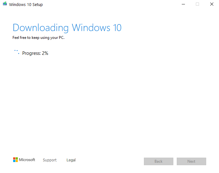
Click on "Next" and the computer will begin downloading Windows.
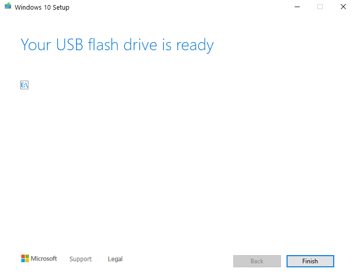
After a while the window will notify you that the USB drive is ready. Click on Finish to close the installer.
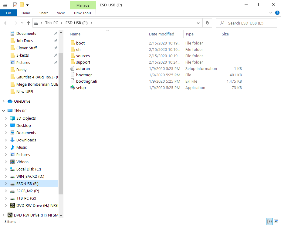
If you'd like you can select the flash drive to see the contents.
Remove the flash drive and set aside for later on post-assembly. You can take it a step further and make a label for it if you have a labelmaker,
Tools
Ensure you have enough space to assemble the components into the case. It's beneficial that the floor is somewhat simple in case you drop small, dark screws. You can get additional tools to assist you in the entire process. I recommend different-sized Phillips-head screwdrivers, Velcro ties, and a magnetic tray if possible. The Velcro ties will help keep bundled wires and cables together, and the magnetic tray will help organize screws and standoffs.
I recommend two or three different-sized Phillips head screwdrivers for the majority of the components and case. A flathead screwdriver will come in handy as well. A powered screwdriver will speed things up a bit, but you'll want to typically hand-tighten most components unless specified.
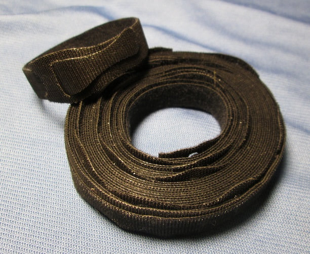
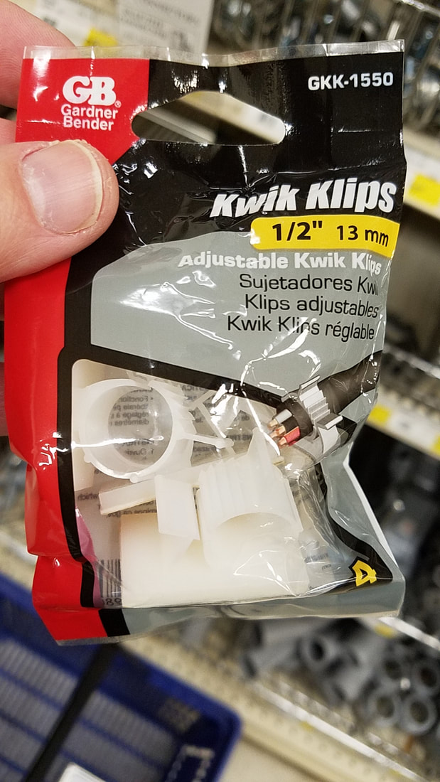
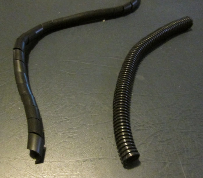
Cable management will come into play here too. While not required, these cheap items will help keep cords and cables out of the way. You'll be able to see components in the case clearer, be able to make easier adjustments without some cords in the way, and you may get better airflow and ventilation overall. Velcro ties (left) come in spools and can be reused frequently. The cable clamps (center) have a flat, adhesive backing and come in a few sizes to accommodate small and large bundles of cables. The cables in the pieces can be locked in place and unlocked when needed. Cable wraps (right) also come in different sizes. The photo here shows two types with the spiral cut (left) and center cut (right). They're equally flexible but I prefer the spiral cut as it's easier for me to get cables in and out of the wrap itself. The center cut wraps are trouble as I have to put pressure on it in order to get the cables to remain in the wrap at first. Each wrap typically comes in a spool but can be cut to size according to your needs.
I recommend two or three different-sized Phillips head screwdrivers for the majority of the components and case. A flathead screwdriver will come in handy as well. A powered screwdriver will speed things up a bit, but you'll want to typically hand-tighten most components unless specified.
Cable management will come into play here too. While not required, these cheap items will help keep cords and cables out of the way. You'll be able to see components in the case clearer, be able to make easier adjustments without some cords in the way, and you may get better airflow and ventilation overall. Velcro ties (left) come in spools and can be reused frequently. The cable clamps (center) have a flat, adhesive backing and come in a few sizes to accommodate small and large bundles of cables. The cables in the pieces can be locked in place and unlocked when needed. Cable wraps (right) also come in different sizes. The photo here shows two types with the spiral cut (left) and center cut (right). They're equally flexible but I prefer the spiral cut as it's easier for me to get cables in and out of the wrap itself. The center cut wraps are trouble as I have to put pressure on it in order to get the cables to remain in the wrap at first. Each wrap typically comes in a spool but can be cut to size according to your needs.
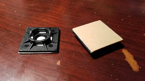
You can use Zip ties, but I only suggest using these for permanent places such as the back of the case behind the motherboard. If you use these, look into Zip Tie mounts, similar to the cable clamps above. These too have an adhesive backing and allow more cables to be secured to other parts of the case.
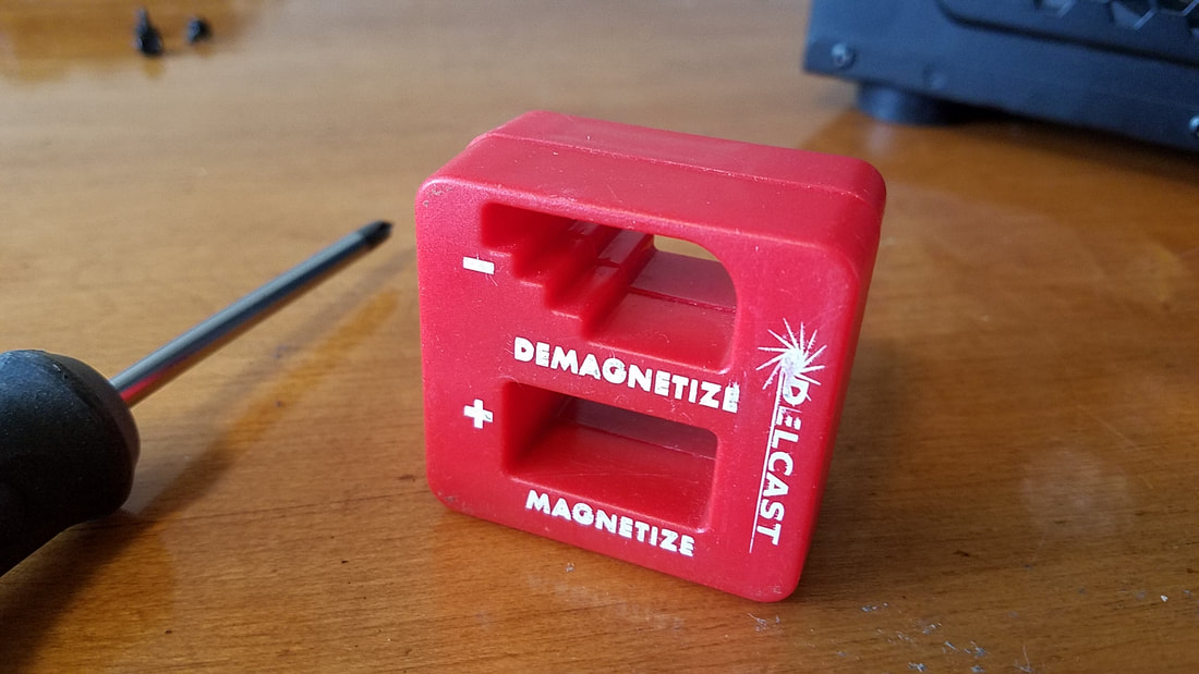
When working in the case you will have times when your space is restricted when tightening or loosening screws. To reduce the chance of dropping screws, purchase a magnetizer/demagnetizer at Harbor Freight or local hardware store if possible (left). Insert the tip of your screwdriver into the MAGNETIZE section and roll it around for a while. Move it nearby screws and small metal parts and you'll see it's benefit immediately. I bought this one on eBay a few years back for under $5.
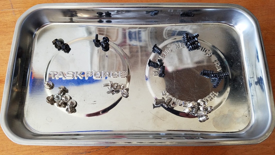
To keep such pieces from rolling off the table, I also recommend getting a magnetic tray (right). Some come as small bowls while the photo below shows a rectangular tray. The tray/bowl is not magnetized as a whole: only the main part such as the circular indentations above where the magnets are located are magnetized.
To keep such pieces from rolling off the table, I also recommend getting a magnetic tray (right). Some come as small bowls while the photo below shows a rectangular tray. The tray/bowl is not magnetized as a whole: only the main part such as the circular indentations above where the magnets are located are magnetized.
|
|
If your workspace includes a clean floor with a solid color or design, basically nothing marble-y or "busy", it will be easier to locate any small pieces if they fall off of the table. The magnetic tray can be waved across the floor to help find and pick up screws if they drop:
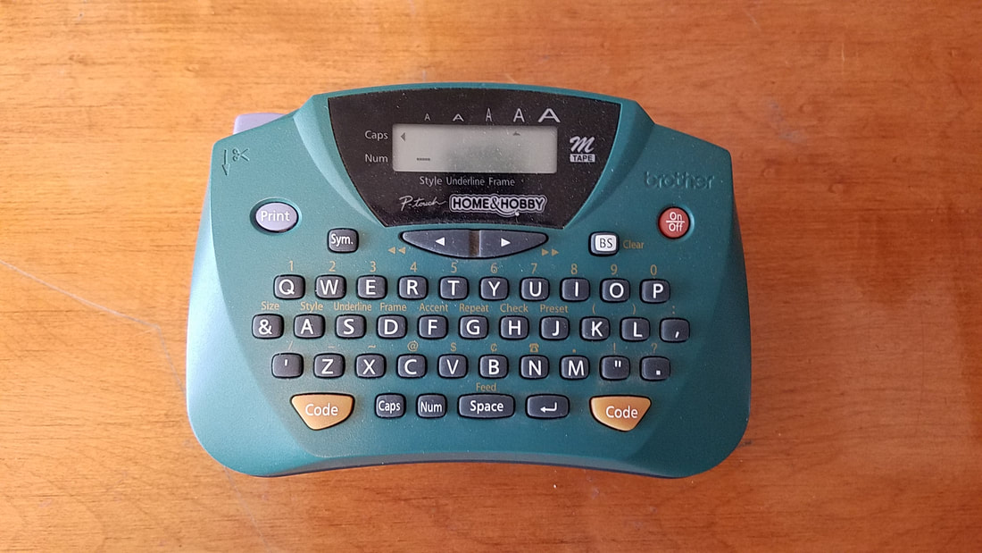
If you have a number of additional hard drives you'd like to add, I recommend picking up a cheap labelmaker as well. You can print and trim the labels to fit on the drives for faster identification when moving them around. The labels can also help when affixed to SATA cables but can become flimsy after some time.
Motherboard and CPU
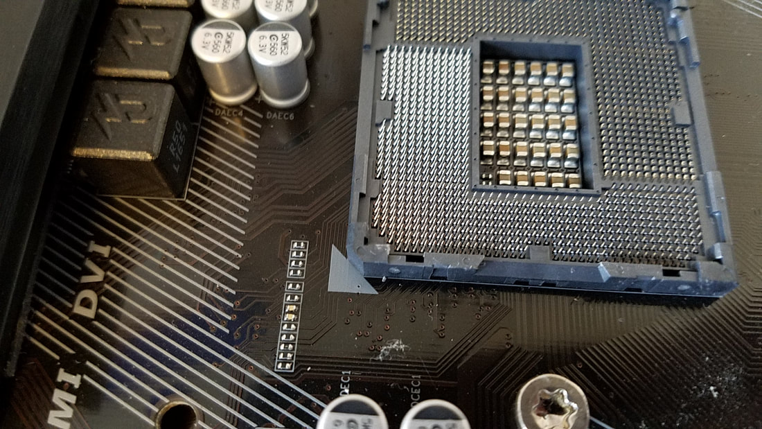
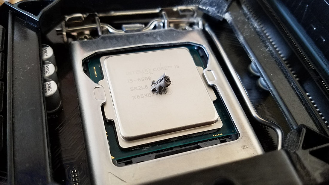
First we can work on applying the CPU and components to the motherboard. It'll be easier to work on the board while it's outside the case first. Remove your motherboard and place it with the slots closest to you. In the photo below, the CPU is already added. Motherboards have a plastic shield over the socket to protect the fragile pins that make contact with the CPU.

The secured latch keeps the socket lid closed. Move the lever out of the way (typically to the right) and lift it, moving it towards the back. Moving the lever up and back from you will also lift up the lid when you move it. When the cover is lifted completely, remove the plastic shield to expose the socket and pins:
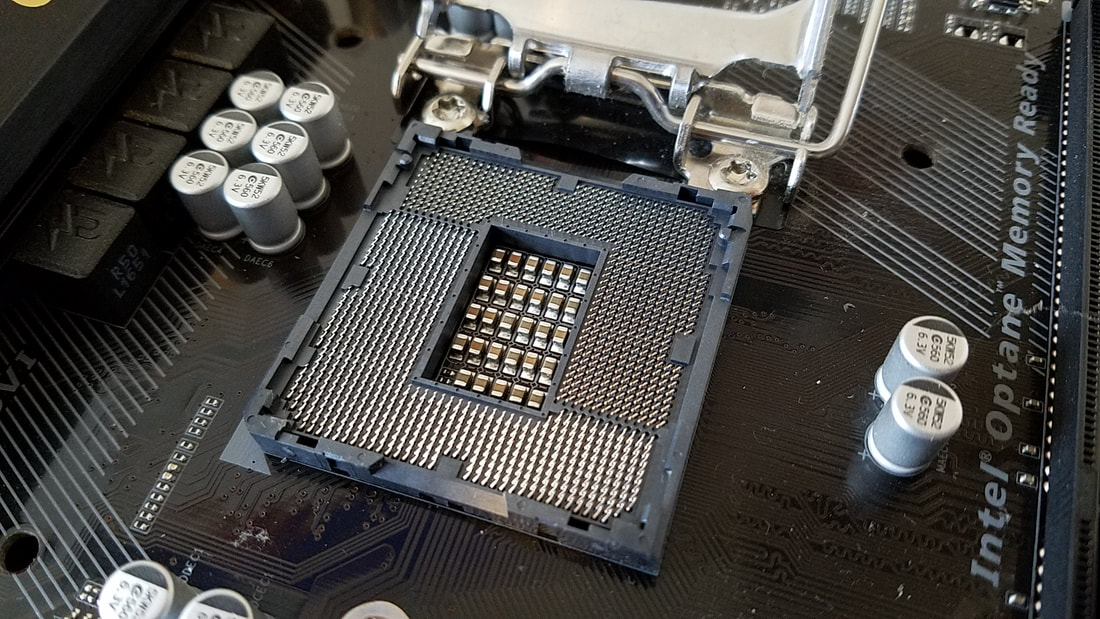
UNDER NO CIRCUMSTANCES ARE YOU TO TOUCH THE PINS! These can easily be bent but not-so-easily unbent, and if they cannot be fixed the motherboard can no longer be used. Please note that AMD processors and motherboards have the pins and holes reversed. That is, the sockets on AMD boards have holes while AMD processors have pins underneath that get fitted in the holes. The warning here still applies that the pins on the AMD CPU should not be touched.
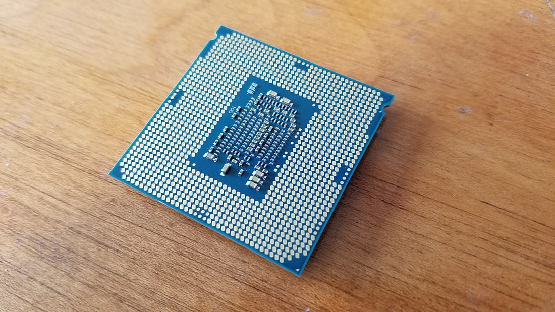
Remove the CPU from its package and plastic. Turn it over and you can see the contacts on the underside:
Remove the CPU from its package and plastic. Turn it over and you can see the contacts on the underside:
Flip it back over right side up:
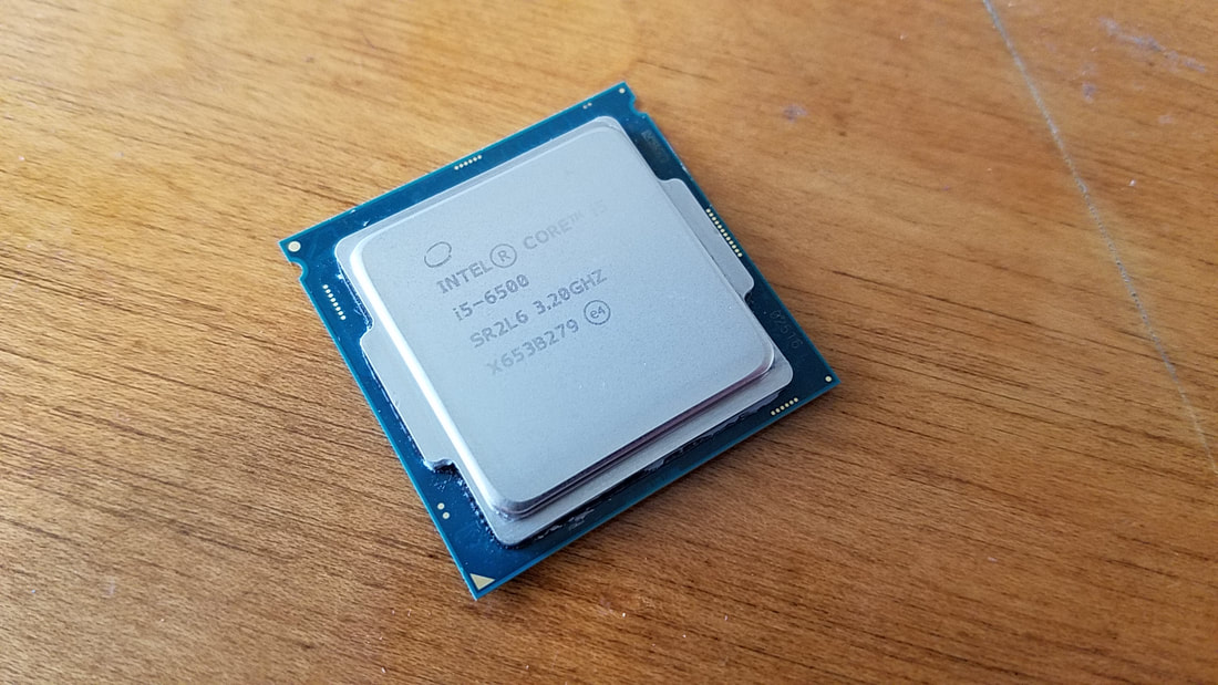
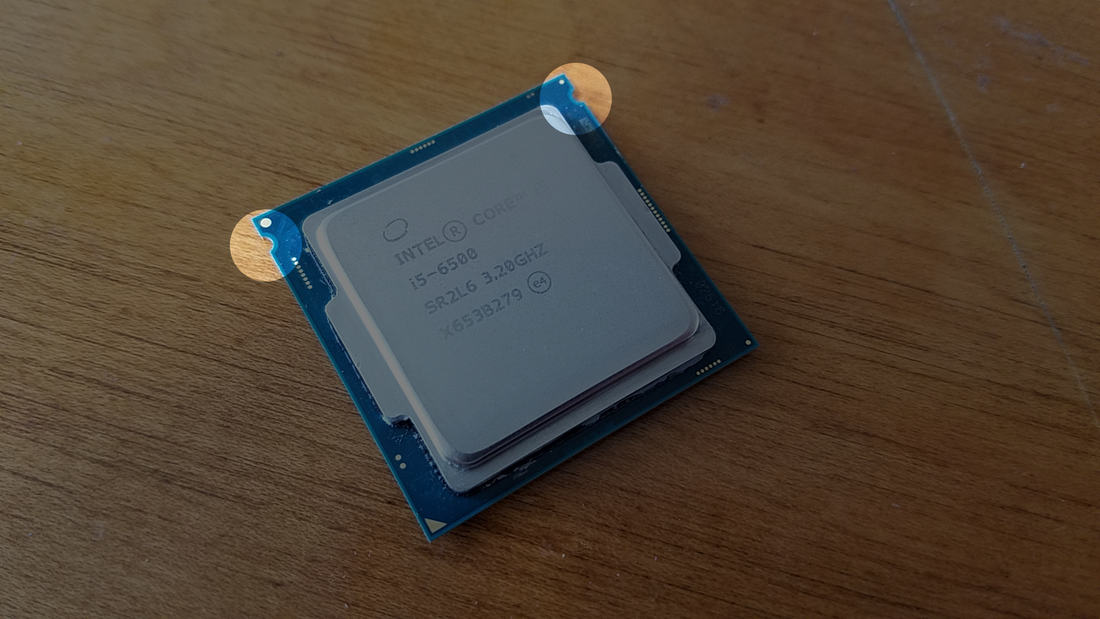
CPUs are designed to be affixed to a socket only one way. In the photo above, the CPU has notches on the upper sides:
...along with a triangle indicator on the bottom corner:
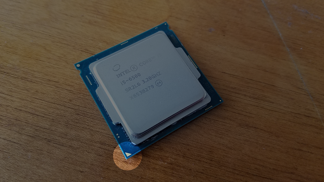
Now if you look back at the CPU Socket on the motherboard you'll find a matching triangle notch to indicate the orientation:
The next steps are shown in the video, but this is a reminder that the video demonstrates the installation of the i-series 6th generation CPU. Other processor installation techniques will vary if it's an AMD or other Intel type processor. Gently place the CPU on the socket ensuring that the notches on the socket line up with the upper half of the CPU, and that it rests easily and evenly on the socket. Once it sits securely you can start lowering the cover over the CPU making sure it's still seated properly.
(YouTube video below: CPU-to-socket)
When you lower the metal cover it will pull the lever forward a bit. Adjust the cover so that the flange makes contact underneath the top of the bolt top, then pull the lever forward, move the right and push it to the left underneath the cover to secure it (as seen in the video). This will ensure the CPU is secure and locked in the socket.
Adding RAM
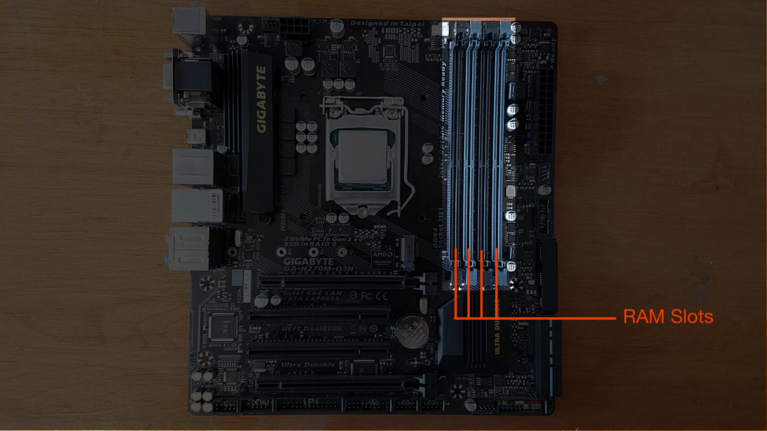
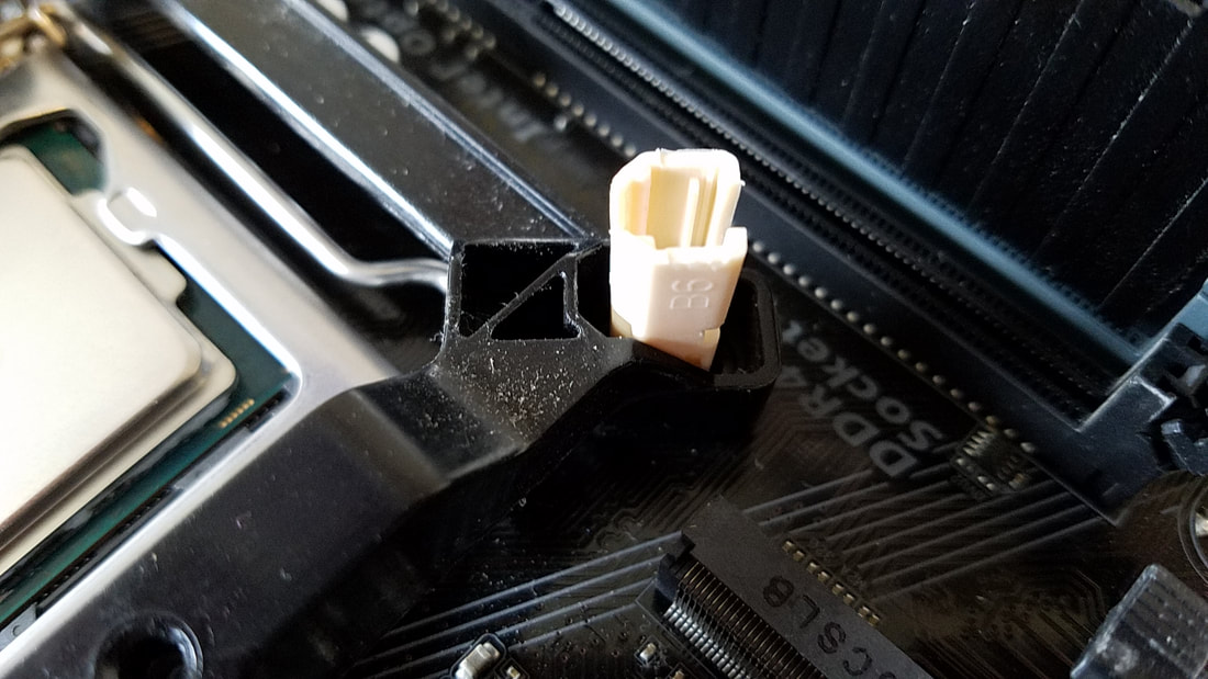
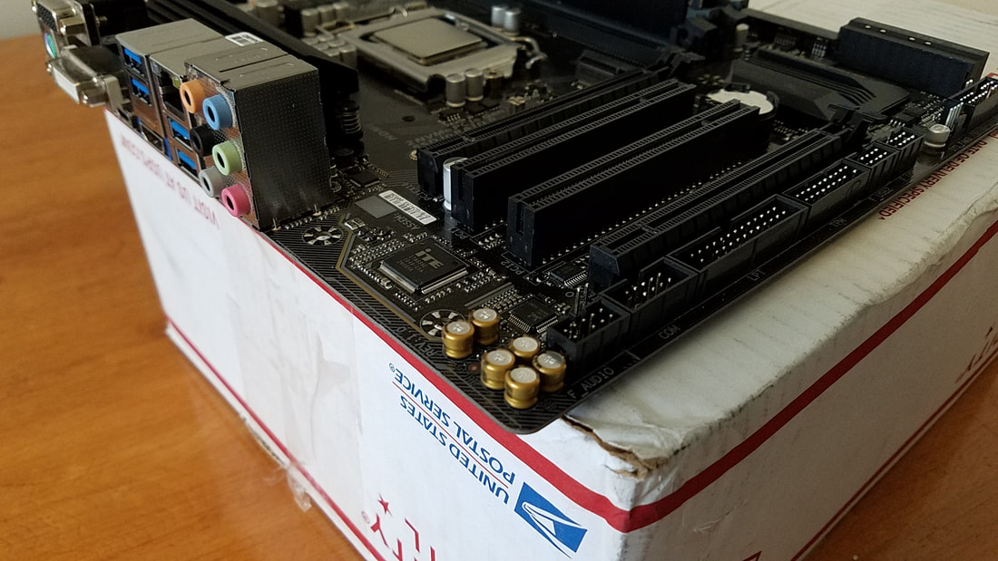
We still have to apply thermal paste and a cooler on the CPU, but in the meantime we can get less-bulky components out of the way to make it easier to install the other parts. Let's start with the RAM. The photo below shows that my motherboard has four RAM slots.
It would be easy to just simply put the modules in any order, but PC assembly is structured in a way to yield better performance when things are done in a set order. RAM works better in pairs as I mentioned previously. Because of this, motherboards are labeled as to the slots for correct insertion. The photo below shows slot 4, 2, 3, and 1: the even-numbered slots being a shade darker than the other slots:
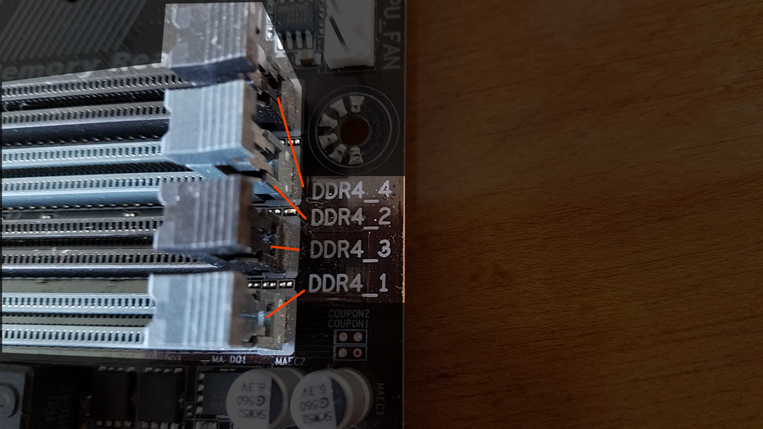
If your setup involves a single RAM module, the best approach is to insert it into slot 1. Otherwise if you have matching pairs the correct approach would be to insert the modules in slots 1 and 2. Any additional modules would go in slot 3, then slot 4.
Note: The photo above also has the label of "DDR4". This tells the user that the slot only takes DDR4 memory. Some motherboards have a combination of memory slots, meaning a few boards may have two slots for DDR4 RAM and DDR3 RAM. In those instances the selection type would equate to only one type of memory that could be used; either DDR3 OR DDR4, not both at the same time.
The next step is to match up the module with the tab in the slot:
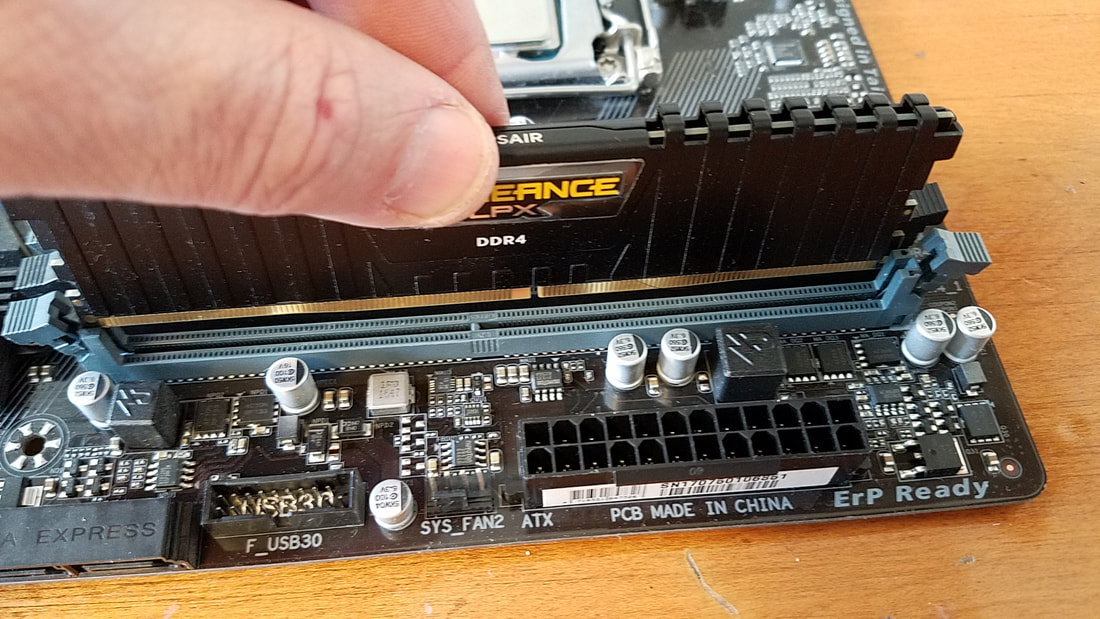
Take another look and you'll see that the module is inserted the wrong way:
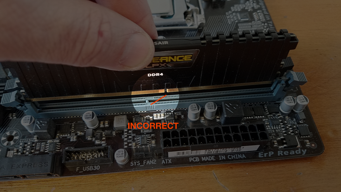
If this happens, simply flip it around first. Ensure the tabs on both sides of the RAM slot are fully opened, then line up the connectors to the connectors on the RAM slot. It works better by pushing it in on each side first after the module is resting on the slot. When you press down on the RAM module, the slot tabs will close up:
If you have a matching module, repeat the process in the same manner. Here's the procedure shown from the other side:
M.2 Drive
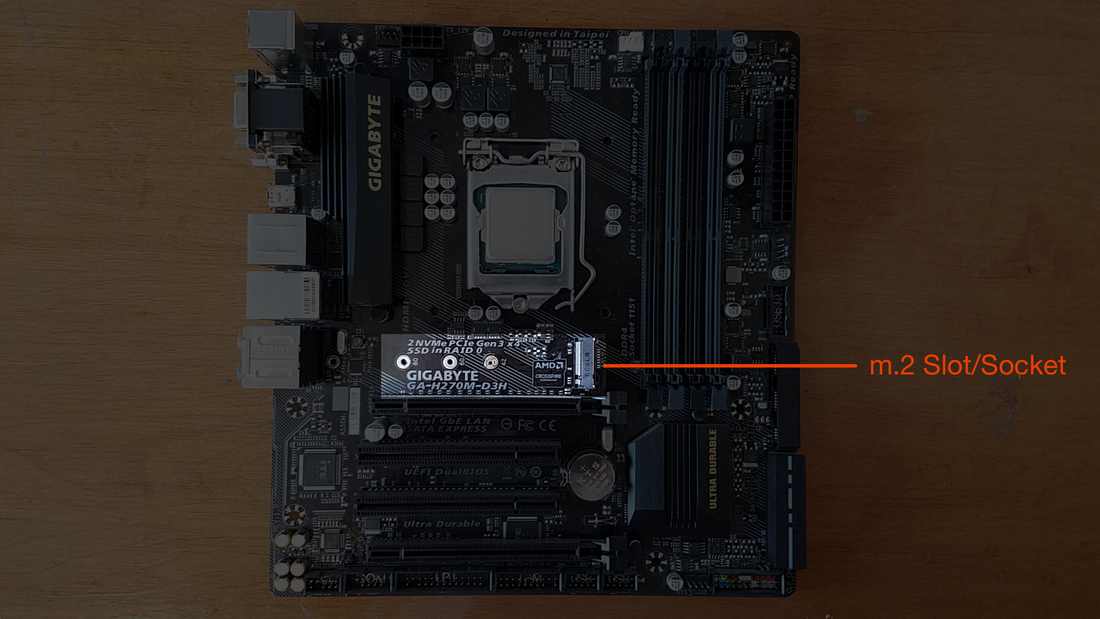
An m.2 drive is best installed before installing the CPU cooler as the location where it gets places is sometimes interfered with the CPU Cooler. Some coolers are bulky in size, and with some motherboards like the one below, accessing the m.2 slot is difficult to access after the cooler is installed.
Here's a closeup of the slot:
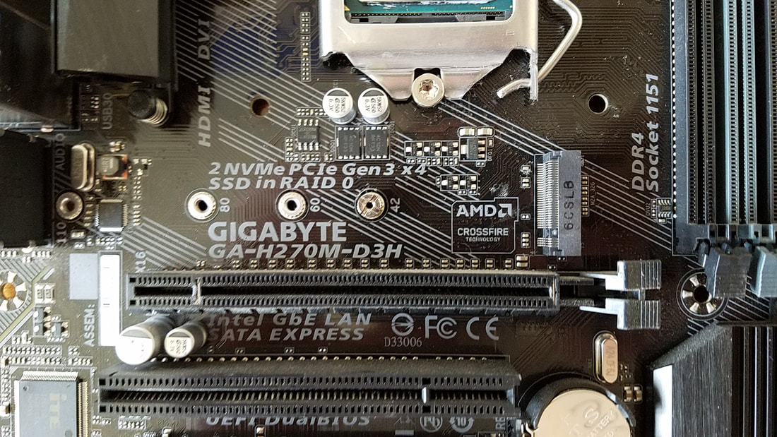
The m.2 slot has three standoffs and a screw. In the above photo, the screw is in the "42" hole. Each hole designates the the length of the m.2 solid state drive.
First remove the screw, then insert the m.2 slot at a small angle and slide the pins into the connector (right of the "AMD Crossfire Technology" logo, in this example). Push the drive in further to the connector to ensure complete connectivity, push the drive downwards to make it level with the connector, then apply the screw and tighten it to secure the drive to the motherboard.
First remove the screw, then insert the m.2 slot at a small angle and slide the pins into the connector (right of the "AMD Crossfire Technology" logo, in this example). Push the drive in further to the connector to ensure complete connectivity, push the drive downwards to make it level with the connector, then apply the screw and tighten it to secure the drive to the motherboard.
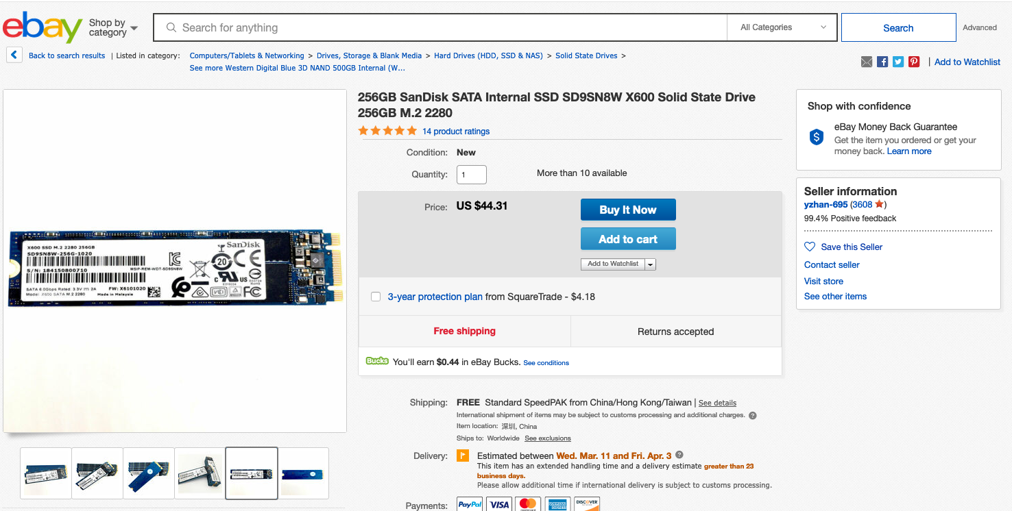
Note: m.2 drives are standardized, and the numbers on the drive provide this data. In the eBay ad below the drive is shown as "2280". "22" is the measurement of the width (millimeters), while the "80" is the measurement of the height. So the motherboard will also take 2260 and 2242 drives. If you look closely in the above photo to the left, there's also a screw slot with "110" labeled next to it, indicating the board will also accommodate 22-110 drives. This is a good indicator that it is future-forward, ready to accommodate longer drives for a much higher capacity.
CPU Cooler
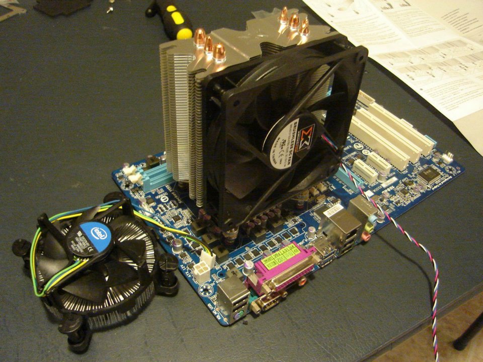
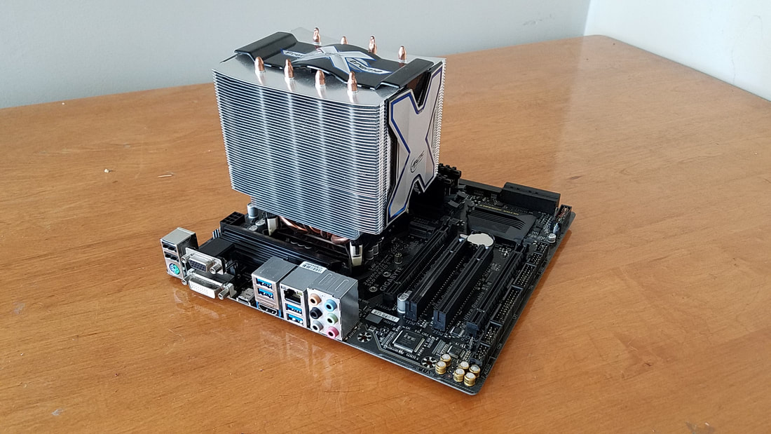
The next step is to affix the cooler, stock or aftermarket, to the CPU and motherboard. Stock coolers do the job, but compared to aftermarket coolers they are typically smaller, a bit noisier, and move less air. Some aftermarket coolers allow for two or three fans for more airflow too. Here's an aftermarket cooler on my older motherboard compared to the stock cooler (left).
Before affixing the cooler to the CPU and board, you need to apply thermal paste on top of the socketed CPU which will dissipate any generated heat to the cooler. If you're using an AMD or Intel stock cooler out of the box similar to the one above, there should be a film of paste already applied to it. Therefore you can skip the step of manually applying paste and affix the cooler to the board. The cooler should have come with an instruction book on how to apply it. I don't have photos or steps here because AMD and Intel coolers differ based on the board and generation, even though the process is about the same. The motherboard will have four holes around the CPU, each hole used for a post for the cooler. Start with one corner and push the post through, then do the same for the post diagonal to it, then repeat the steps for the remaining two posts. Each post on the cooler can be turned in order to loosen it so that the cooler can be removed.
On stock coolers, the fan is designed to blow air toward the side of the case (when you're looking down at the inside). Some aftermarket coolers have the same design, but the majority of coolers are designed with an attached fan that aims toward the back and exhaust hot air.
On stock coolers, the fan is designed to blow air toward the side of the case (when you're looking down at the inside). Some aftermarket coolers have the same design, but the majority of coolers are designed with an attached fan that aims toward the back and exhaust hot air.
The next step involves applying a small dab of thermal paste to the top of the CPU. Now there are various opinions as to how the paste should be applied, whether it's a strip or a dab. I prefer the dab, as pressure from the cooler and heat will dissipate the paste over the entire CPU. You never want to go overboard with the paste though. Use a small pea-sized dab:
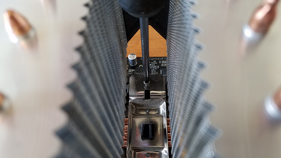
Now check the instructions for your cooler regarding the installation technique. Some coolers require a special backplate that fits over the underside of the motherboard. The specific cooler for my Intel board had me mount a bracket to the board and affix it with posts, but yours may vary:
...then use a long screwdriver and screw the cooler to the bracket. It wasn't the easiest task:
The next step was placing the fan through the cooler:
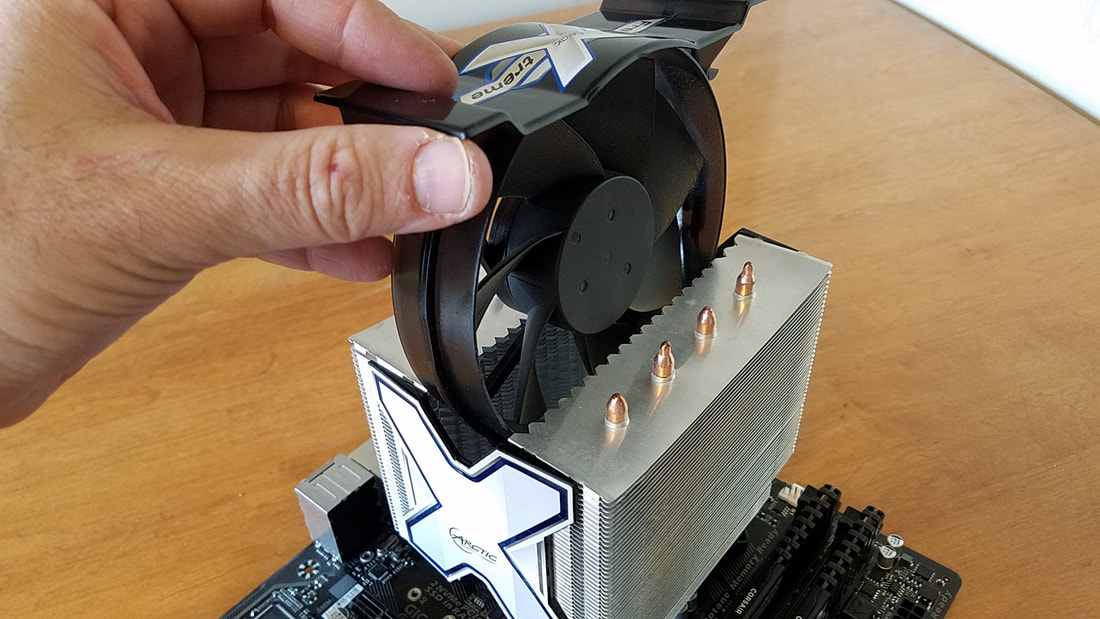
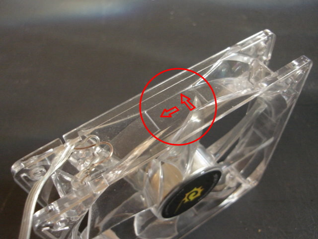
The manual stated the direction where the fan should be aiming at. If your cooler has no instructions, check the fan itself. Most should have two arrows indicating the airflow. Here's a photo of a clear fan with my red highlights indicating the arrows and airflow direction:
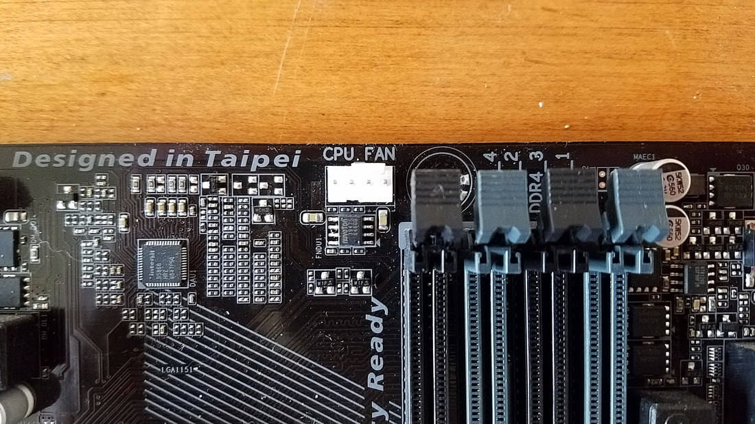
There's a little more to it than that. The wire for the fan connector can sometimes be long, and it helps to route it a certain way depending on the length and where it will connect to. On your motherboard there should be a CPU fan with a label:
With my fan running through the cooler I ran it through like so:
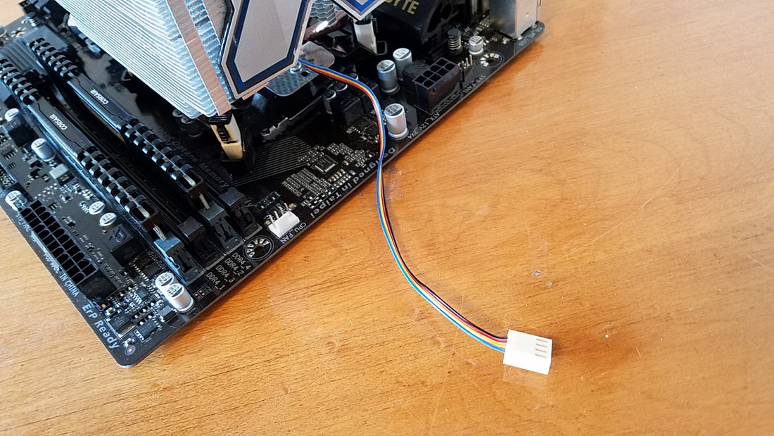
After that I connected the fan connector to the fan header on the board.
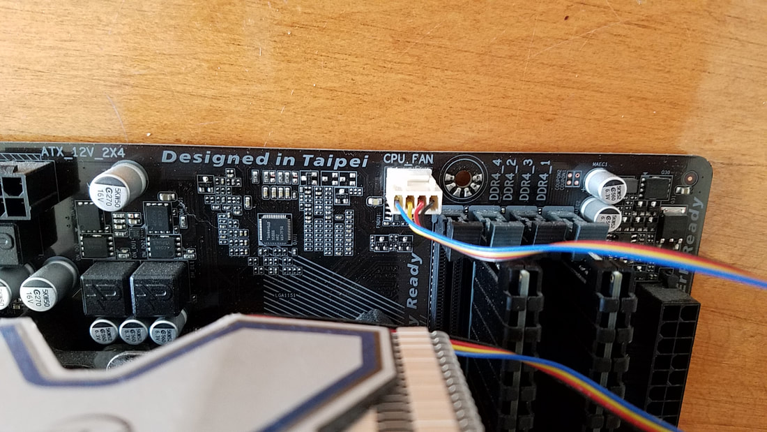
The above photo shows what it looks like in its simplest form. Typically you would want to run the extra length of cable out of the way, or in my case, coil it up around itself once or twice, then connect it to the motherboard. This way the wire will be out of the way but still nearby if it is needed to be removed. With the system partially assembled it looks like this:
Testing
At this phase we're going to need to do a pre-test by hookup other devices and peripherals. This is done so that if something doesn't work right or needs adjusted, it will be much easier to work on the board while it's outside the case compared to the confinement of working on it while it's inside the case.
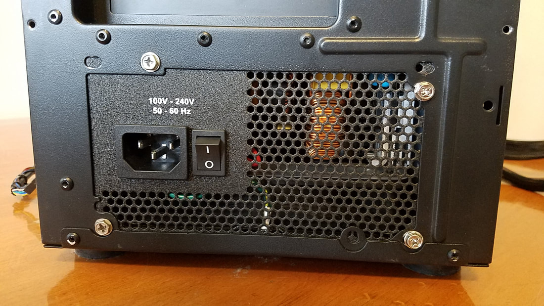
Make sure that your power supply is turned off if it has such a switch. Here's a photo of a PSU in the case with the switched turned to 0 (off):
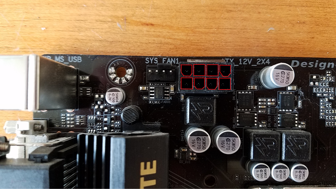
Locate the Main 20/24 pin connector and the 4/8 pin P4 connector on your motherboard. For the rest of the guide, these will simply be referred to as the 24-pin connector and P4 connector. The 24-pin connector is typically located on the right side while the P4 connector is located on the left side near the top, sometimes closer to the CPU:
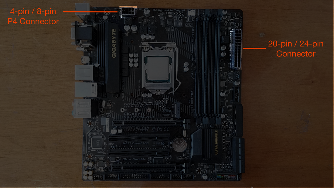
You can refer back to Chapter 3 for the photos of each connector there. Locate the P4 connector on the motherboard. Look closely and you'll notice that the holes in the connector are oriented to fit the same plugs on the P4 cable:
Then connect it to the motherboard like so. In this video you can see that the P4 connector has a tiny lip on the edge of it facing outward. The P4 connector cable has a matching lip to make contact and snap together. I had difficulty trying to hold my phone while recording, and I also attempted to merge the two parts of the P4 connector together as it was being stubborn for me that day:
Then you can take the 24-pin connector and repeat the same for the 24-pin socket on the motherboard:
You'll want to put the motherboard on top of a box or non-conductive surface. This is to prevent damage to the system. Additionally if you have a video card to install you can do that as well. The box is especially needed as the case flange on the video card will overhand and needs to go over the edge of the box or surface. If it's resting ON the box, it may tilt the card and disable the card from making full contact with the motherboard.
On the motherboard near the bottom right hand corner should be a bundle of header pins for the front panel connectors:
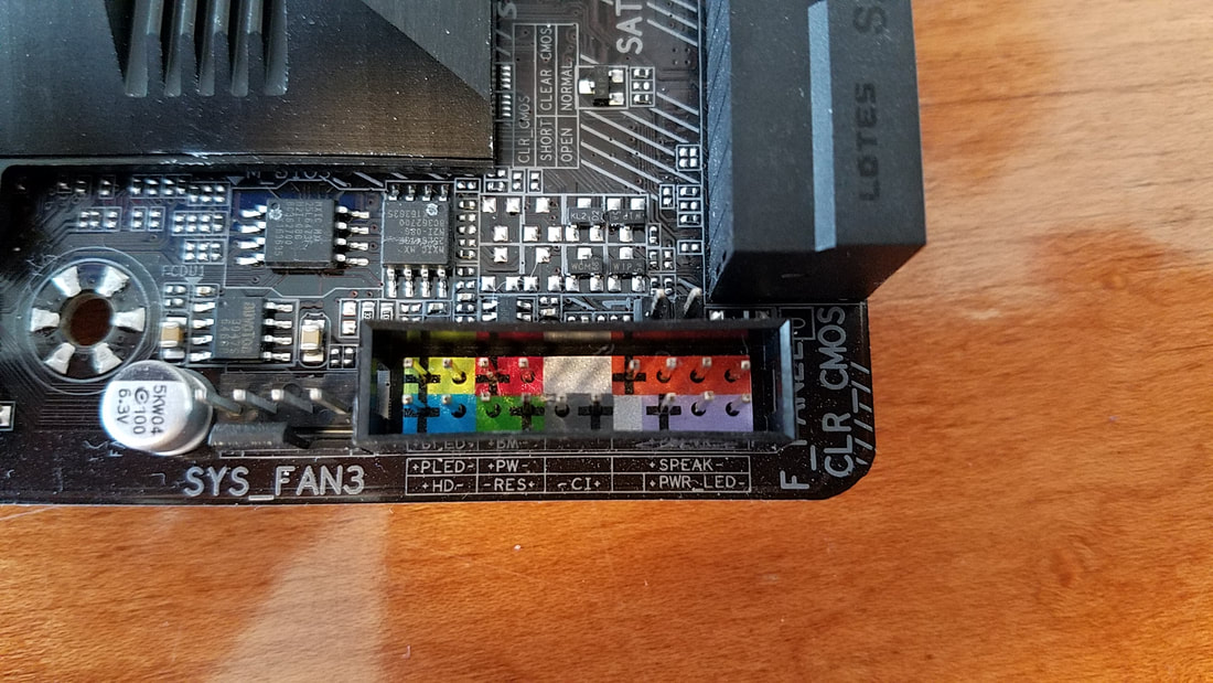
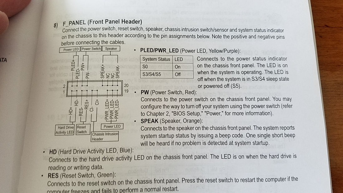
Your motherboard should have come with a tiny speaker. Connect that little speaker to the header section here. This motherboard includes a very tiny legend on the board itself showing the connections. Even up close I could not read it, so I had to take a photograph to enlarge it. You can always check your motherboard owner's manual for a clearer description of the connections:
You'll also notice that the header labels are listed positive and negative.Typically black is ground (negative) and any other color from the wire is hot (positive). The photo above shows how the wires from the front panel get connected, but we will not be connecting these yet as the motherboard will be outside of the case,
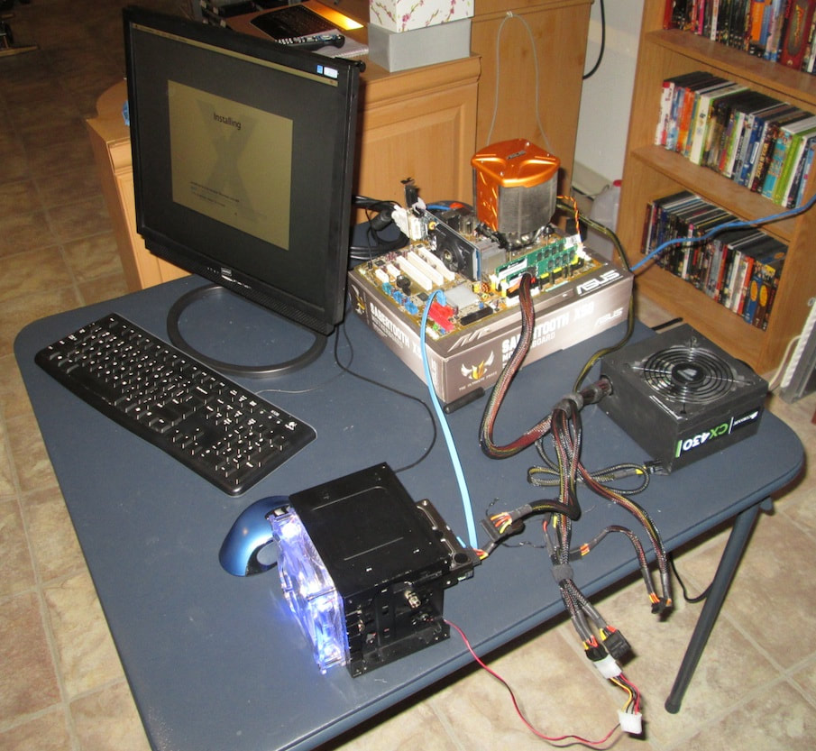
With that done, now hook up a keyboard, mouse, and monitor to your system. Here's an older image I had saved from a Hackintosh I worked on in 2012, showing my setup. By having the components out of the case, I could shut the system down and make adjustments easily if needed.
With that done, now hook up a keyboard, mouse, and monitor to your system. Here's an older image I had saved from a Hackintosh I worked on in 2012, showing my setup. By having the components out of the case, I could shut the system down and make adjustments easily if needed.
Once assembled you can connect a power cord between a wall jack or surge strip and the back of the power supply itself, then turn the power switch of the power supply the 1 (on) position. When you do this it will not turn the computer on just yet. For that you can take a screwdriver and make contact between the Power + and - posts to turn it on:
If there are connection issues such as a missing keyboard or bad RAM, the small speaker should emit a series of beeps. Else any connected fans should start spinning and any lighted components connected should light up. If you heard a beep or tones, do a Google search for PC startup beeps to determine what the error is. Make sure the RAM is properly seated, the keyboard is fully connected, and whatever measures are necessary to resolve the issue(s).
As long as everything is running, you can then shut down the machine. This can be done two ways: holding the screwdriver between the power headers for 5 seconds (same used to turn on the machine, only shorter), or by flipping the switch on the back of the power supply to 0. After the computer is completely off; you can remove the power supply cables from the motherboard and the power cord from the back of the PSU.
As long as everything is running, you can then shut down the machine. This can be done two ways: holding the screwdriver between the power headers for 5 seconds (same used to turn on the machine, only shorter), or by flipping the switch on the back of the power supply to 0. After the computer is completely off; you can remove the power supply cables from the motherboard and the power cord from the back of the PSU.
NOTHING HAPPENS, NO LIGHTS, NO SPINNING FANS
- Check to ensure the power cord to the PSU is plugged in all the way and fits snugly. Remove and reapply it if necessary.
- Ensure the other end of the power cord from the PSU is going to a wall jack or working outlet. If it's going to a surge strip / surge protector, ensure the device is powered on, and also try another open outlet on the strip.
- Look into the case and ensure the two wires of the front panel power switch are going to the two pins on the board for the power leads. If they're not fully inserted on to the two pins it may not turn on.
- While in the case, ensure the 24-pin mains and P4 connector are fully connected. Remove and reconnect if necessary.
- While unlikely, it's possible that the CPU is not firmly seated in the socket and may need adjusted. Remove the cooler, open the gate of the CPU socket, and ensure the CPU is firmly seated.
- If none of the above solutions resolve the problem, try a replacement PSU/Motherboard/CPU if necessary. It's extremely unlikely that a new part can be part of a bad batch as these components go through vigorous testing before being shipped out, but it has happened. If you have a spare component available, test these one at a time to narrow down the faulty component.
